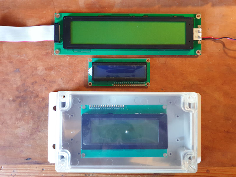
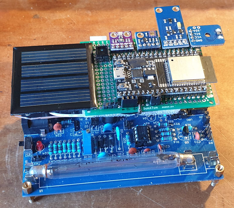
😢 Oh no! The large 40x4 LCD I have is too big for the enclosure I have, and want to use. The next size up enclosure with transparent front is twice the size, so whilst would fit the LCD there would be much wasted space and it wouldn't look right. So I can use a 20x4 LCD that will fit, but only half the display of the big one. I'll use the 20x4 for now and then change to the 40x4 if I find a suitable enclosure. I like the full transparent front and opaque back and sides. Fully transparent and it would look like a glass lasagne dish and I can't see the innards with an opaque front. Having the
-
-
I have just added 'wind chill' to the mix and seems to be calculating correctly. I had to put in some static numbers for testing as wind chill is only valid when the wind is moving more than 3mph (4.83kph/1.34ms) and the temperature is below 10°C. This is the formula: T_wc = 13.12 + 0.6215 * T_a * (0.3965 * T_a - 11.37) * v^0.16 Where: T_wc is the wind chill in Celsius temperature scale, T_a is the air temperature in degrees Celsius, v is the wind speed in kilometers per hour. This is the output with static wind (10MPH) and temp (9°C): Temperature: 9.00 | Humidity: 45.36 | Dew Point: 0.00 |
-
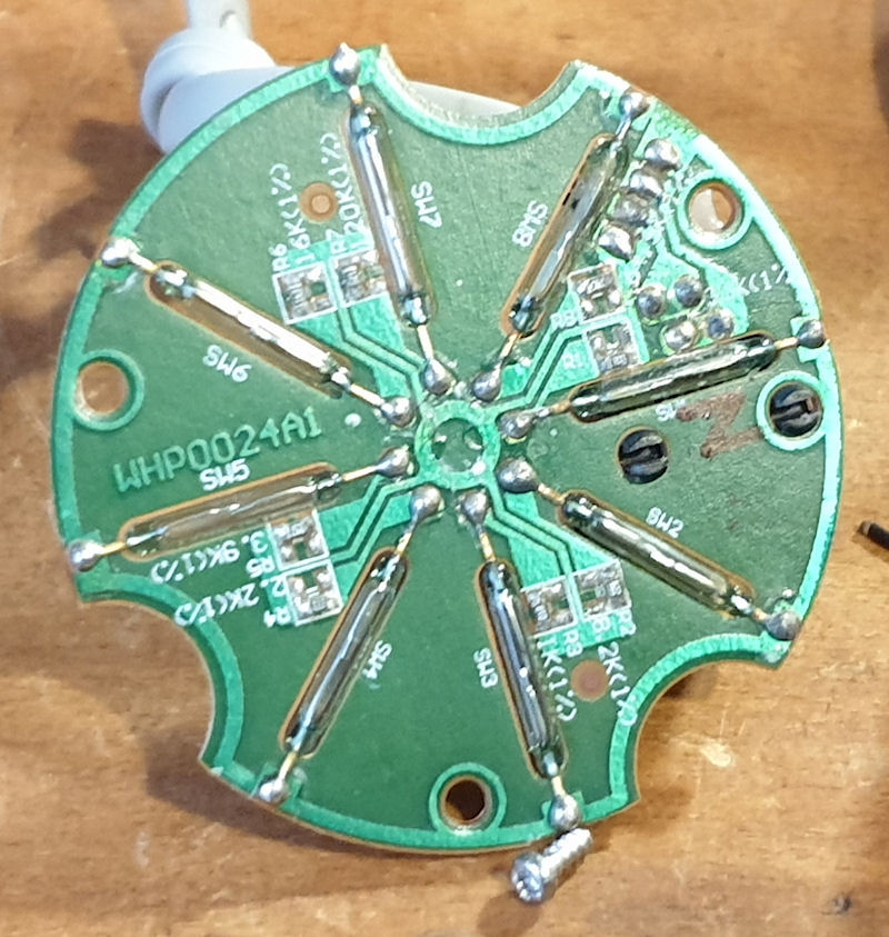
The sensors are good! The electronics are that is. I've checked over the anemometer, wind vane and rain gauge and all are working properly. They are going to need a little work to get them back to shipshape again and I may even pot them in, although the actual board have fared quite well. Only a bit of dull solder on the wind vane PCB. As you can see form the images all the sensors use good, old, conventional reed relays and a magnet on the spinney bit. I may swap these out for hall effect sensors in the future. One thing I would like is a better resolution for the wind vane. As it stands I
-
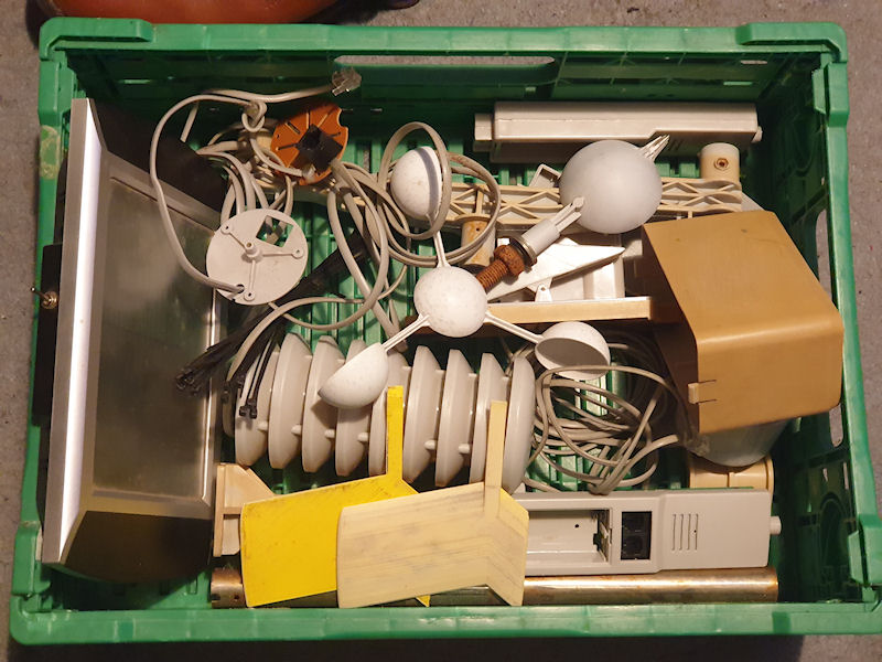
About 4 years ago my weather station failed. It was only a cheap WH1080 from Maplin (remember them?), but it did it's job for about 8 years. The sensors were getting a bit janky and then the transmitter stopped working. I managed to find a replacement transmitter in China and that did pair with my receiver, but I think the receiver is also broke, or the two aren't quite compatible as I can't save the settings on the receiver and Cumulus is telling me that it is getting some duff data. Now it lies in pieces as shown in the picture. Next stop.... the scrap bin. Goodbye old faithful cheapo
-
I have been meaning to write an update as I have added a couple of new sensors. One of which is my very own invention - straight from the old grey matter. I have also made some improvements and things seem pretty stable. I have improved the web pages for displaying the data and is now easy to go back and forwards day by day to view the data. For some reason the ESP32 started counting something like 10x the actual counts from the counter. I think this happened after I added an AS7341 sensor, or something. I have had other issues with the ESP32 slowing to a crawl. I guess this is what happens
-
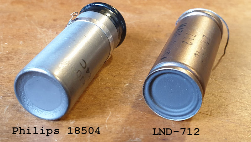
Both tubes are α, β & γ - the Philips 18504 can also be used to detect neutrons if the tube is wrapped in Cadmium foil of about 0.5mm. I recently bought a Philips 18504 tube for about £30 (all in) on ebay from Bosnia. It is very similar to the LND-712 so I wanted to compare them. I knocked up a testing rig so the testing could be identical for each tube. All sources were measured at 1cm from the window on the tube. I used a RH Electronics Arduino IDE Geiger Counter DIY Kit ver.2 that I modified to give a pulse output. That goes into an ESPGeiger Log that I used for reading a 5 minute
-
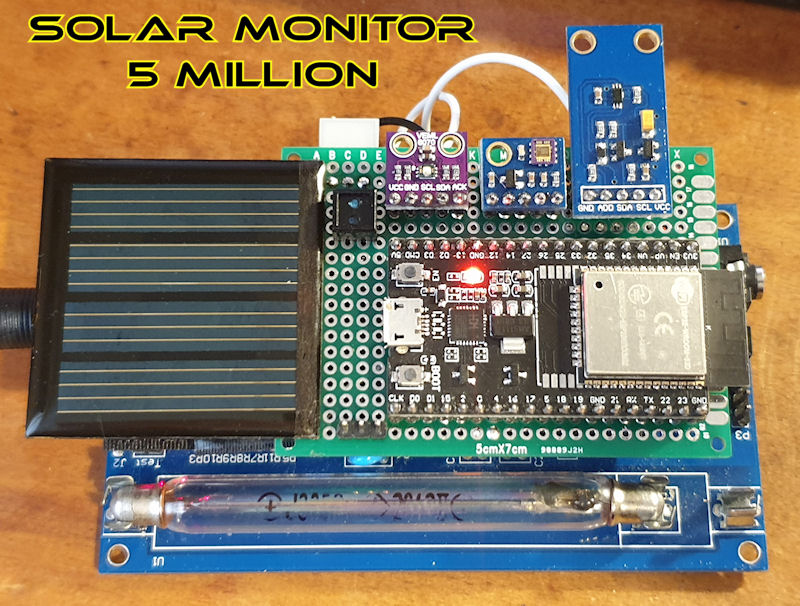
Solar Monitor 5 Million I have been meaning to write this up for a couple of weeks now, and I finally do it. This is an experiment I am conducting (very loosely at present) that came about from leaving my CAJOE RadiationD-v1.1 with J305by on my window sill for a week and noticed a strange pattern with the 'excess' counts. They were stronger in the morning than in the afternoon, even to the point they were stronger than in direct sunlight. I mentioned this to a couple of members here and we all agree that it is strange, and that we all expected there to be more counts in direct sunlight than
-
I knocked up a simple monitor to easily see if radmon.org is up or down. It uses an ESP8266 (Wemos D1 mini clone) and a single RGB LED. It simply polls radmon.org by asking for a response from the server. If it gets the reply it is expecting in a timely manner it lights the LED green. If it doesn't get the reply it wants, or times out, the LED changes to orange and sets a fail counter +1. If it receives the correct reply again it goes back to green, but after 3 consecutive failures the LED lights red. There really isn't much more to it. There are positions in the code where an alarm or
-
I have been testing a new GM tube for the past few days, a Robotron 70 013. Its quite a sensitive tube at around 100 CPM for background count. I got to thinking "would a more sensitive tube last as long as a less sensitive tube" so threw some numbers together to find out. My Initial thought was "if the more sensitive tube clicks more, then surely it wears out faster." I'm comparing the SBM-20 (~20 CPM background) with the Robotron 70 013 (~100 CPM background) The SBM-20 has a life of around 20,000,000,000 pulses. The Robotron has a life of around 60,000,000,000 pulses. That settles it, right?
-
- Posted on
- Featured Image
Below is a list of conversion factors for GM tubes that I have been collating over time. They may come in handy if you are building your own Geiger counter and want to convert from CPM (counts per minute) to μSv/h (micro sieverts per hour.) RH = values from RH Geiger SBM20 0.006315; SBM20 0.0057; - RH SI29BG 0.010000; SI29BG 0.0082; - RH SBM19 0.001500; SBM19 0.0021; - RH STS5 0.006666; STS5 0.0057; - RH SI22G 0.001714; = 583.43 SI3BG 0.631578; SBM21 0.048000; LND712 0.005940; SBT9 0.010900; SBT9 0.0117; - RH SI1G 0.006000; SBM-20 - conversion factor 220 CPM -> 1uSv/h (working voltage-