- Posted on
- Featured Image
-
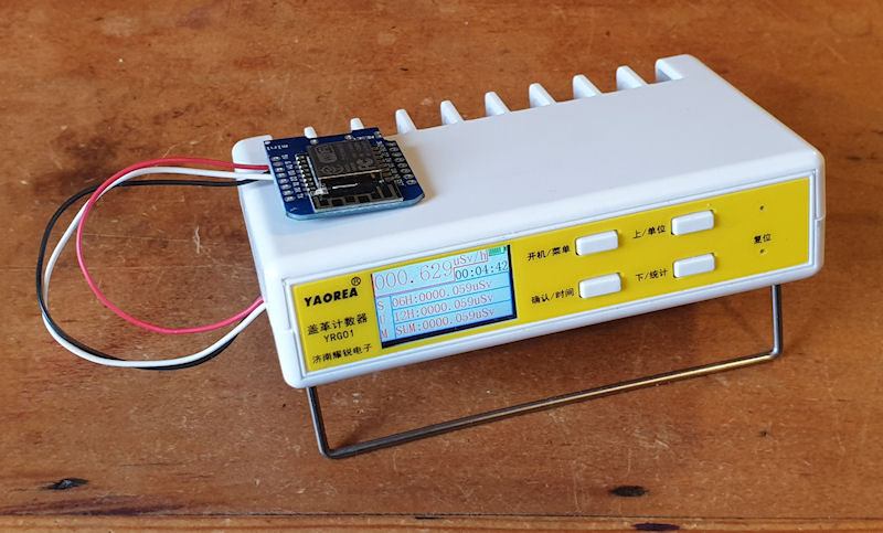
A very kind gentleman recently sent me an outdoor BME280. It is a smaller version of the BME280 breakout board, but in an outdoor enclosure. It was sent with one very simple instruction: "For Radspod One." I think it is like this one from AliExpress but there seem to be a few different types so have a look about. Not too long ago, Steadramon added capability to ESPGeiger for the BME280, BMP280 and I think the BME680, but don't quote me on that. Anyway, as it was intended for Radspod One, and now ESPGeiger firmware supports the BME280, it would be very rude not to! So I did. 😁 It was all quite