- Posted on
- • Geiger Counters
A Very Strange Geiger Counter from Russia - The BIR-3 Pt.2
- Author
-
-
- User
- Mr Blinky
- Posts by this author
- Posts by this author
-
I have managed to power this up and it does work! 😊 I have also started reverse engineering it a little. I removed the two (brass?) strips and replaced them with wires so I can flatten the board out properly. The two strips were connecting the ground and VCC on the boards together. I haven't yet translated the manual, but I will in due time as I can't find a single thing about this counter on the internet at all and the info may be of use to others' too. In all it seems like a very basic counter with a quirky display. If I knew what the ICs actually were I could maybe replicate this on a breadboard. One of the ICs I now have some clue with, but not the one on the HV/detector board.
First, here is a video of the unit working. This is running from a 9v battery just pushed against the terminals on the bulb connector. It will run from a 3.6v LiPo cell also, but the sounder and LEDs are quite weak, although it does actually detect radiation fine at that voltage.
Interestingly, the orange LED doesn't light orange, but red. The camera picks this up as a different shade of red, but there is little difference to my eye.
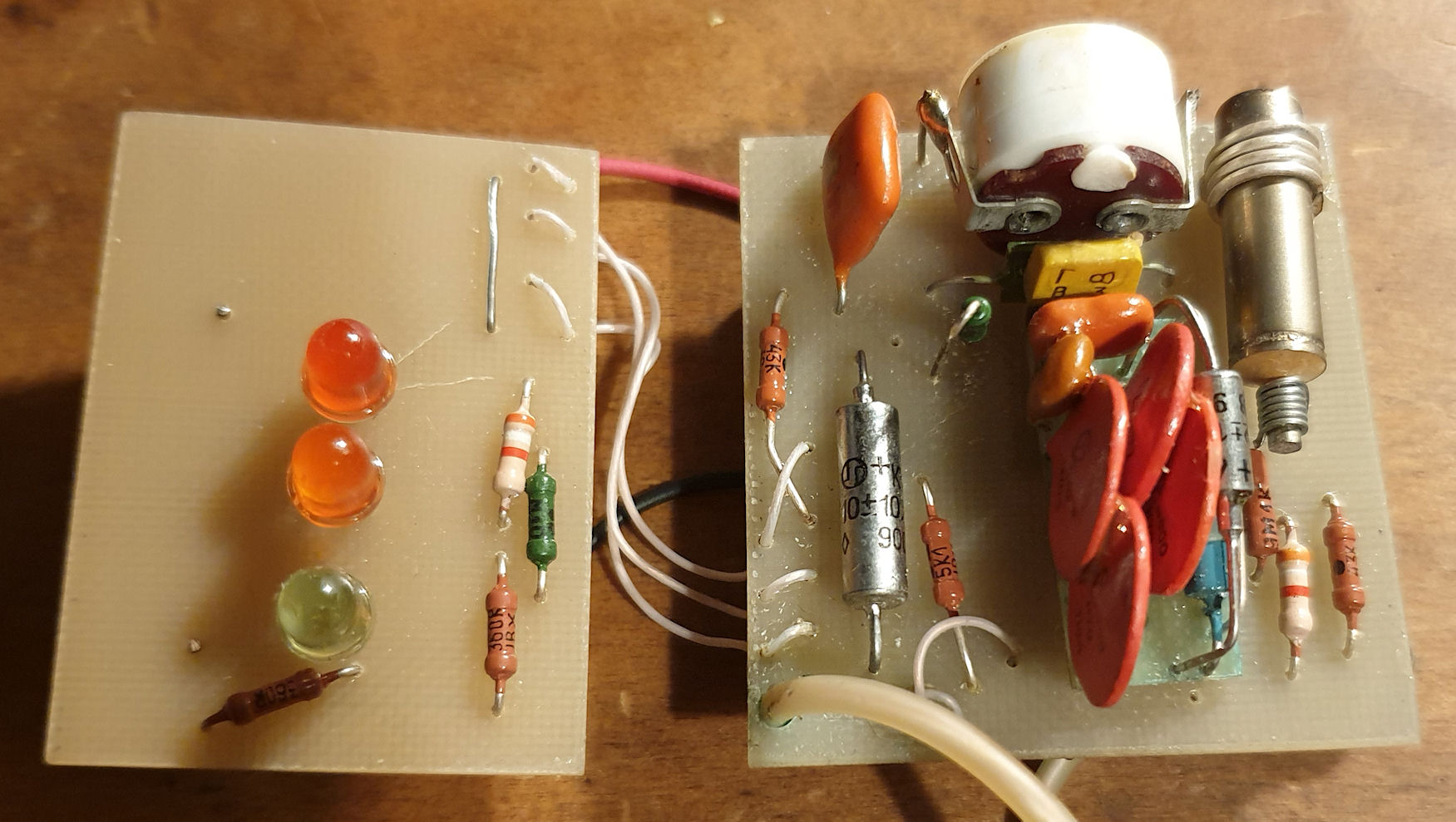
I have identified each type of component. The packages whilst similar to the common packages we know of, these seem quite crude in their composition, even for 1990. But this was probably designed and built in the communist USSR era, so would explain that with it being 'domestic' kit.
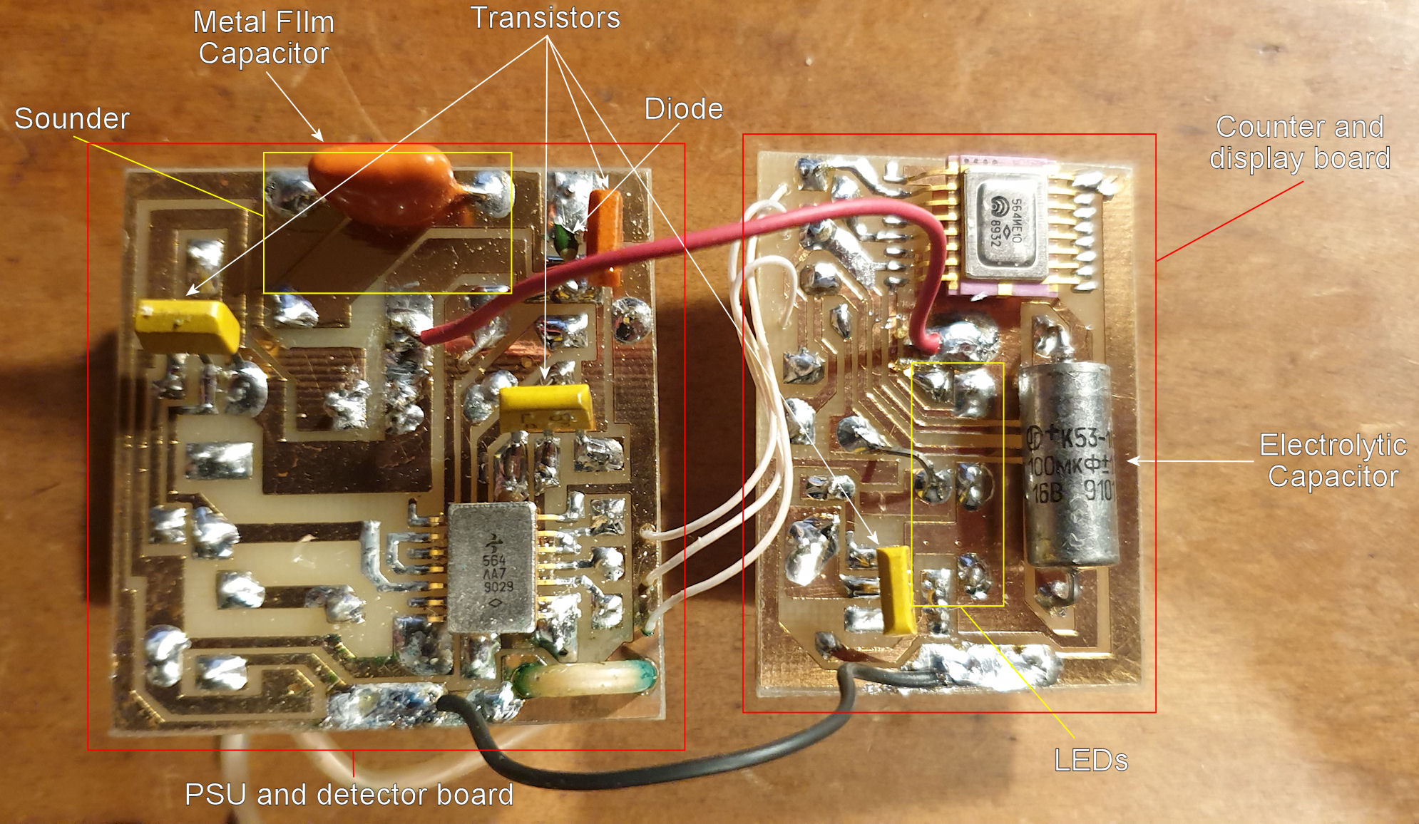
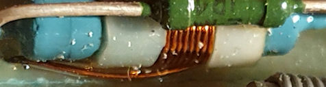
This is the HV PSU with transistor tagged on the end. It is a separate board piggy-backed onto the detector board. As the tube is an SBM-10 (verified as measurements are exact against my known SBM-10) then my assumption is that the HV board generates around 400v. Below that is what I think is the HV transformer. It looks like a coil wound around a wire-wound resistor - very creative! There are diodes that are hard to see next to the large disc capacitors on the HV PSU. This would be a simple pulse generator and voltage quadroupler circuit (two voltage doublers in series.) Hmm, I wonder if that IC on the detector board is used as a ring oscillator to trigger the transistor on the HV PSU? That's plausible.
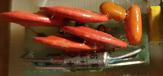
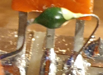
Below is a transistor, and next to that a small signal diode. Probably similar to a 1N4148 but looks to be the same on the HV PSU board, so they may be higher voltage than that. Maybe something like a 1N4004 or 1N4005.
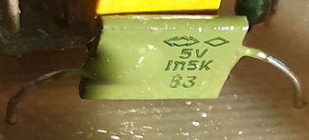
Now, this component got me for a while, until I started tracing the circuit. I'm pretty sure this is a 5V Zener diode (I could be wrong.) This is in series with the sounder. From what I can tell the signal goes into a resistor, then the 5V Zener, then the sounder. This would make sense if the sounder was rated at 5v with a supply higher than that, such as my 9v battery.
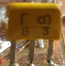
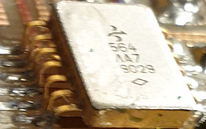
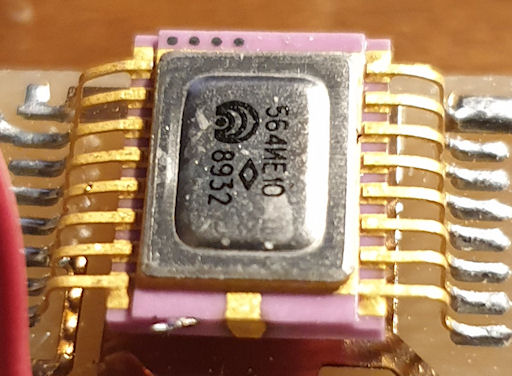
And finally the two ICs. The first is from the HV and detector board. I have little idea what this is or does. It resembles something of a ring oscillator, but there is a lack of capacitors for that. It is much of a puzzle but may be the oscillator for the HV generation. I would have to reverse engineer the actual circuit for that (which I may do in time.) Whereas the 2nd IC is on the display board and I am pretty sure that is something like a logic binary counter. I come to that assumption from the pattern of the LEDs. orange comes on, goes off, red comes on, goes off. both stay off for a bit and both come on, then it starts again. 4-bit binary counter maybe? Its interesting as if I remove the source when an LED is lit they just stay put, as would happen with a binary counter.
I really need to translate the manual as I think that may add some details that I'm missing. Its all quite interesting. 😄
Archived from radmon.org - originally posted 05/02/2022
Add Comment
This policy contains information about your privacy. By posting, you are declaring that you understand this policy:
- Your name, rating, website address, town, country, state and comment will be publicly displayed if entered.
- Aside from the data entered into these form fields, other stored data about your comment will include:
- Your IP address (not displayed)
- The time/date of your submission (displayed)
- Your email address will not be shared. It is collected for only two reasons:
- Administrative purposes, should a need to contact you arise.
- To inform you of new comments, should you subscribe to receive notifications.
- A cookie may be set on your computer. This is used to remember your inputs. It will expire by itself.
This policy is subject to change at any time and without notice.
These terms and conditions contain rules about posting comments. By submitting a comment, you agree with these rules:
- Although the administrator will attempt to moderate comments, not all comments can be moderated at all times.
- You acknowledge that all comments express the opinions of the original author and not those of the administrator.
- You will not post material which is knowingly false, obscene, hateful, threatening, harassing or invasive of privacy.
- The administrator has the right to edit, move or remove any comment for any reason and without notice.
Failure to comply with these rules may result in being banned from submitting further comments.
These terms and conditions are subject to change at any time and without notice.
Comments