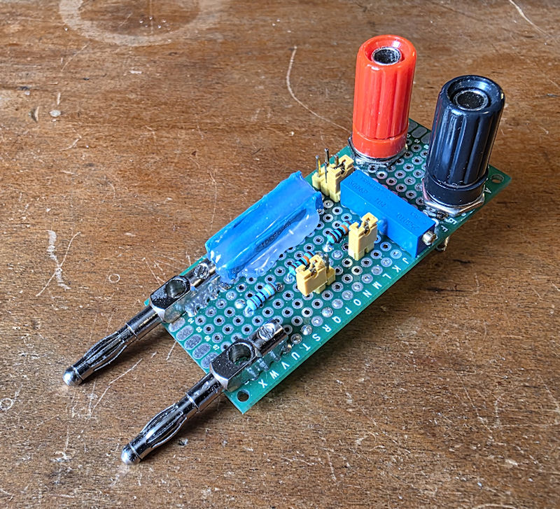
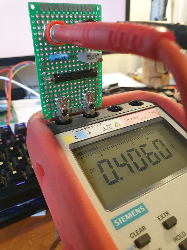
I recently got a new multimeter that has a slightly higher burden than the meter I was previously using. This meant that the original voltage divider I made wouldn't calibrate to my new meter. The solution was to increase the resistance of R2 in the divider. On the v1 divider R2 was made up of a 1MΩ and a 100KΩ trimmer pot in series. To increase the R2 in the v2 divider I added a couple of 100KΩ resistors in series with the 100KΩ trimmer pot. R2 became 1MΩ + 100KΩ + 100KΩ + 100KΩ (pot) all in series. I added two jumpers alongside the two new 100KΩ resistors so I can put them in circuit or
-
-
If you have ever used Radlog Pro from radmon.org, you will know that the only way to get the counts into it is via serial. This is generally fine if your counter sits near the PC Radlog Pro is running on, but if not it can be a challenge. Simply making a long serial cable works providing you can route the cable. The other method is wirelessly. I used to use a wireless TTL serial transmitter and receiver. It worked for the most part, but the signal was always an issue. Even receiving the signal in direct line of sight, through glass was a challenge for these little units. After servicing my
-
Some time ago I threw together (what I thought was) a 1000:1 voltage divider for measuring the HV on Geiger counters. This consisted of a Dale 1% 1G ohm resistor (R1) mounted all nice in a box with big chunky gold banana connectors and another quality 1% 1M ohm resistor (R2) connected to a banana socket and then a bunch of croc leads flying about. It worked, but wasn't right. I hadn't accounted for the multimeter's own internal resistance (known as a burden on a circuit). I'm pretty sure my multimeter is a 20M ohm resistance, or thereabouts, so that made R2 actually 950K ohm when the meter
-
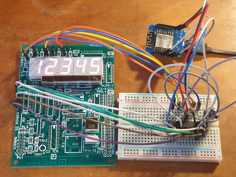
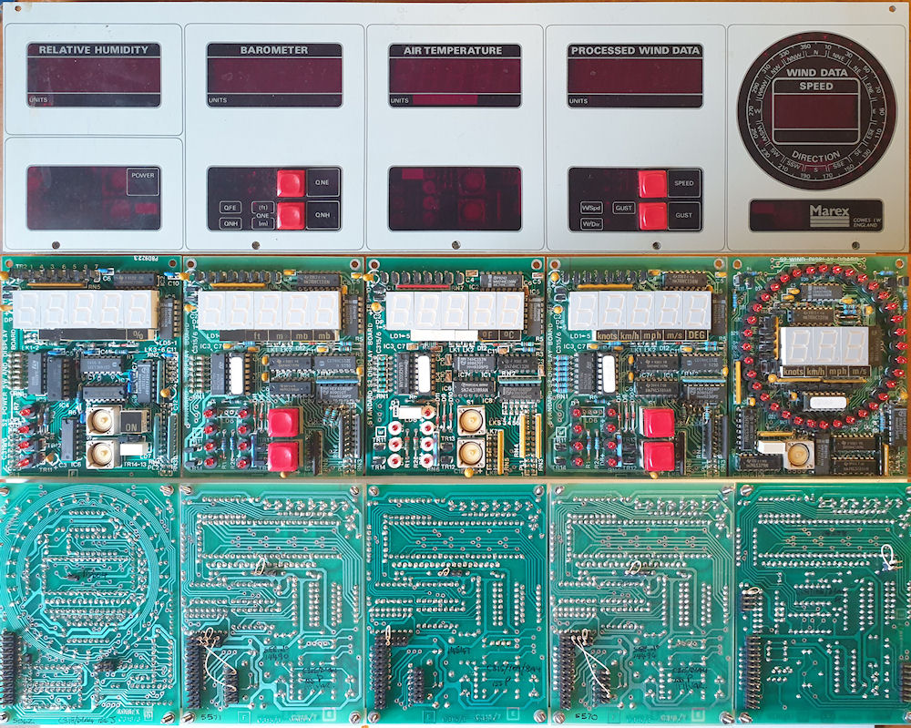
Update #5 Progress!!! 😊 MAX7219 LED controller (for common-cathode LEDs) running common-anode 7 segment displays. The brightness isn't quite what I could like, but it should be fine. I may be able to tweak it a little, but the MAX7219 wasn't really designed for running common-anode, so if not, I can't complain. Now to make up a little daughter board with the MAX7219 and try it out for fitment/space etc. If all is good, then I'll make some more and get the display boards retrofitted with the new controllers. This IC will daisy chain too, but I might have to get a little clever with the code as
-
This time I get out my I Never Won A Blue Peter Badge badge, a stack of foam board, some sticky tape, more sticky tape, some hot glue, some recycled fabric insulation stuff from a dishwasher and knocked together a box for insulating the heat absorbing temp sensor. Not much really to say about the construction. I think the pictures say it all. This is the end product and really does appear to work well. It managed to record a temperature of just above 70°C a few days ago. 😯 That's about 20°C more than before it was in the insulated box. It still needs some small tweaking as when I open my
-
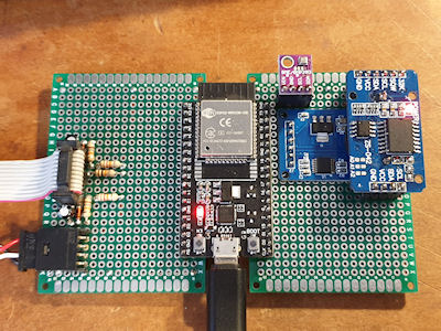
Update #4 My head still hurts.... But I am making progress. I have added an RTC ( DS3231 ), a micro SD card and a GPS receiver ( NEO-6M GPS Module ). The RTC is just for keeping time and date. The RTC will be set every hour, or 24, or whenever, to the GPS time. I need to have a think about UTC/BST for recording and displaying. Do I record everything in UTC and have adjustment on display, or do I set the RTC twice a year into UTC/BST and record using UTC/BST. The latter would be the most beneficial for displaying and graph creation, but with a caveat that 1 hour of readings will get screwed up
-
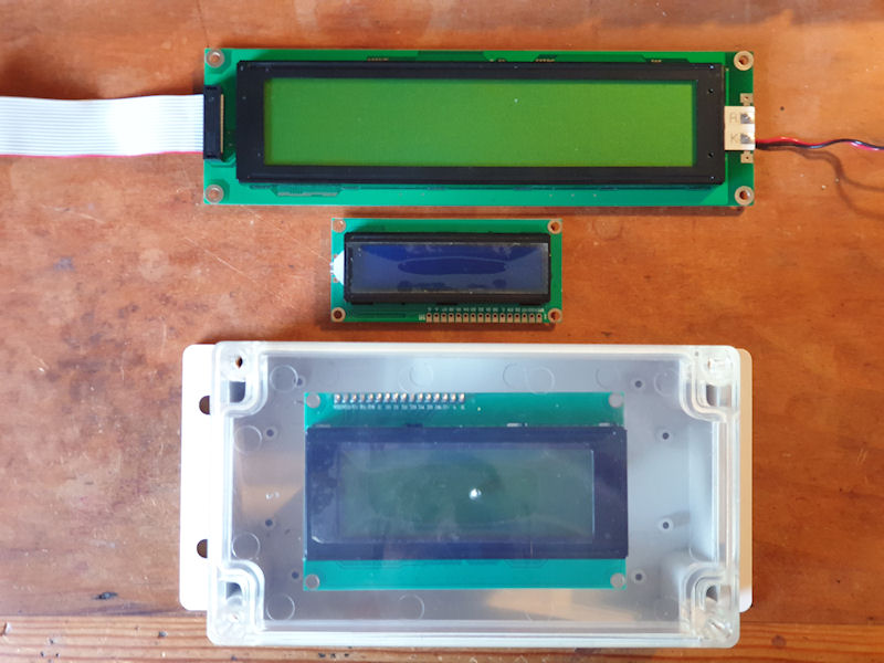
😢 Oh no! The large 40x4 LCD I have is too big for the enclosure I have, and want to use. The next size up enclosure with transparent front is twice the size, so whilst would fit the LCD there would be much wasted space and it wouldn't look right. So I can use a 20x4 LCD that will fit, but only half the display of the big one. I'll use the 20x4 for now and then change to the 40x4 if I find a suitable enclosure. I like the full transparent front and opaque back and sides. Fully transparent and it would look like a glass lasagne dish and I can't see the innards with an opaque front. Having the
-
I have just added 'wind chill' to the mix and seems to be calculating correctly. I had to put in some static numbers for testing as wind chill is only valid when the wind is moving more than 3mph (4.83kph/1.34ms) and the temperature is below 10°C. This is the formula: T_wc = 13.12 + 0.6215 * T_a * (0.3965 * T_a - 11.37) * v^0.16 Where: T_wc is the wind chill in Celsius temperature scale, T_a is the air temperature in degrees Celsius, v is the wind speed in kilometers per hour. This is the output with static wind (10MPH) and temp (9°C): Temperature: 9.00 | Humidity: 45.36 | Dew Point: 0.00 |
-
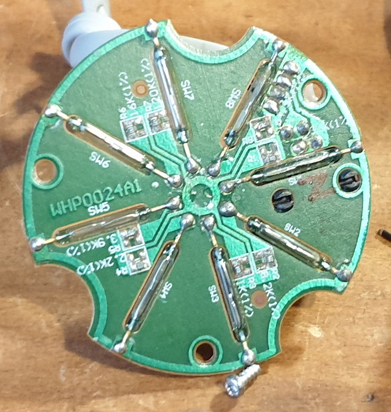
The sensors are good! The electronics are that is. I've checked over the anemometer, wind vane and rain gauge and all are working properly. They are going to need a little work to get them back to shipshape again and I may even pot them in, although the actual board have fared quite well. Only a bit of dull solder on the wind vane PCB. As you can see form the images all the sensors use good, old, conventional reed relays and a magnet on the spinney bit. I may swap these out for hall effect sensors in the future. One thing I would like is a better resolution for the wind vane. As it stands I
-
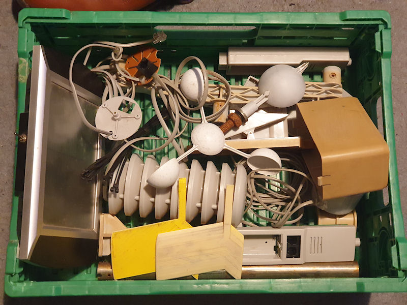
About 4 years ago my weather station failed. It was only a cheap WH1080 from Maplin (remember them?), but it did it's job for about 8 years. The sensors were getting a bit janky and then the transmitter stopped working. I managed to find a replacement transmitter in China and that did pair with my receiver, but I think the receiver is also broke, or the two aren't quite compatible as I can't save the settings on the receiver and Cumulus is telling me that it is getting some duff data. Now it lies in pieces as shown in the picture. Next stop.... the scrap bin. Goodbye old faithful cheapo