- Posted on
- • Other Electronics
New Weather Station Build Pt.4
- Author
-
-
- User
- Mr Blinky
- Posts by this author
- Posts by this author
-
Update #4
My head still hurts.... But I am making progress.
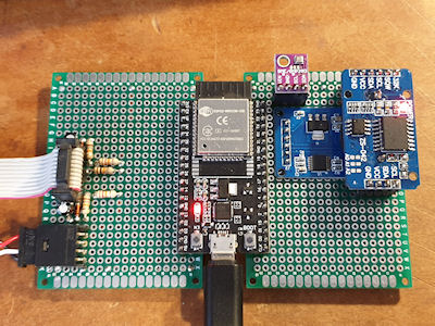
I have added an RTC ( DS3231 ), a micro SD card and a GPS receiver ( NEO-6M GPS Module ). The RTC is just for keeping time and date. The RTC will be set every hour, or 24, or whenever, to the GPS time. I need to have a think about UTC/BST for recording and displaying. Do I record everything in UTC and have adjustment on display, or do I set the RTC twice a year into UTC/BST and record using UTC/BST. The latter would be the most beneficial for displaying and graph creation, but with a caveat that 1 hour of readings will get screwed up when the clock shifts back one hour. Aside from that it would work great and make displaying readings much easier. Only recording in UTC gives a good standard but means that every display has to have the ability to switch from UTC to BST and vice versa, adding an hour, or taking away. The RTC also as an EPROM with each address capable of 1,000,000 writes. That may come in handy if I want to store variables across power cycles. The ESP32 has a flash memory, but is rated for between 10,000 an 100,000 writes so if I were to use flash or EPROM, the RTC EPROM would be the better to use in terms of number of writes.
The SD card is for recording all readings forever, until the card is full and then it can overwrite old days. It will also store data from the past # hours for use in showing trends. It could also log things like sudden changes so they can be looked at later. Of course the PHP/MySQL could also do this. As the time is recorded on the weather station itself it will be easy to upload and readings if the web server went down for any reason. The weather station is becoming more self contained. Where my old weather station would just send readings to Cumulus (software) and Cumulus would do all the number crunching, the ESP32 seems to have enough oomph to do all the number crunching too. Having it this way simplifies things and makes for a better reliability as it is not reliant on a PC running.
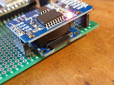
I added the GPS for a few reasons; It has very accurate time and can be used to set the RTC. It is faster than NTP (as in the data is already there in the ESP32, no need to fetch it), requires less programming and resources, is not reliant on the internet and rules out any misconfiguration. I'm also thinking about the future. This weather station could quite easily be mobile, or in a place where there is no internet. The weather station will also record the Lat and Lon and elevation. This could be used if the station was somehow mobile. The elevation data can be used in the fuzzy feels like formulas. The station will also record the number of satellites and HDOP (horizontal dilution of precision (quality of the GPS data/precision.)) The TinyGPS++ library also has a couple of interesting examples for tracking satellites and recording their elevations, but I am unsure if this data would be of any use.
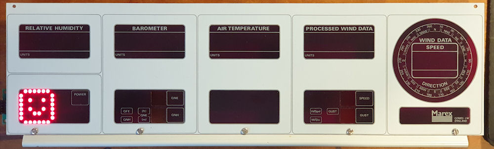
I have also been bashing away at the code and pulling it all together. I still have to dig out my large LCD screen and program that and fix two fuzzy feels like formulas. And I have to fix the weather vane, but I am waiting on parts for that. I don't know what material to use for the tail. I would like something like a waterproof foam board, that can be sanded and profiled. Something that is strong enough to cope with the wind and rain, but also light enough. My 2nd version of the tail was made from balsa and even with a good few coats of paint it only lasted a couple of years. The 3rd version was 3D printed and whilst looking great, it was too heavy. And then there is the Marex display too. I have been looking at that a little and seems I should be able to drive the 7 segment displays and other LEDs too without too much work. The 7 segment displays are all common anode and it looks like the MAX7219 IC will drive them with some extra footering. This IC could also be used for the wind direction indicator. I could use an Arduino Mega and drive each wind direction LED individually! 😂 I may have to do something like that depending how the circuit arrangement with the LEDs is.
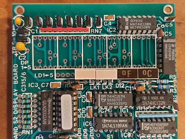
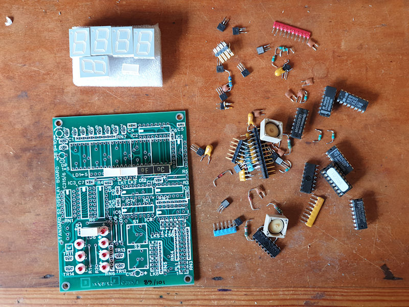
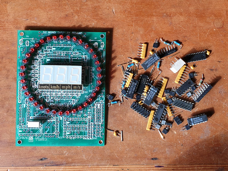
This is the temperature display board and all the cathodes for the 7 segment LEDs are all wired in parallel, leaving the common anodes separate. So each segment is wired together but the anode for each is separate. Two of the decimal points are wired to jumper header pins on the back and some decimal points are not connected to anything. I think a MAX7219 IC, an Arduino Pro Mini and a handful of passives should be enough to get each display module working. I would probably have to do the wind direction indicator and the display as two separate MCUs, so a total of 6 Arduino Pro Minis and 6 MAX7219 ICs, a ESP32 or ESP8266 to get the data over WiFi and whatever passives it needs. I can drive 4 7 segment displays directly from an Arduino with 4 transistors and some passives, but not 5 sadly. Also the MAX7219 has current limiting built in, so I can adjust the brightness and requires little other than the IC itself. I think I will completely strip the boards down to everything except the LEDs and button switches and that should give me enough of a clean slate to work with. Keeping the old PCBs and modifying them also keep all the positions of everything good.
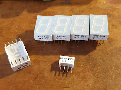
Some LED goodness. The 7 segments are all made by HP and the small rectangle ones are made by Broadcom. They are all still available today. Seems all to good parts got put into this unit. This Marex display would have been a small fortune back in it's day. I have a date too on this unit. It is a 1994 vintage, but the youngest IC in there is a 1993 vintage and the oldest looking to be 1982.
Update #4.1
I have stripped down the air temperature and wind direction/speed boards. I think I am going to have to do a lot of work with the wind direction indicator LEDs as they are common'd in 3x 10 and 1x 6, which isn't going to work with the MAX7219 ICs, so I suspect a lot of chopping tracks and wiring will be needed on that. It does look like 7 segment LEDs should be much easier. I just need to test some code that apparently makes the MAX7219 work with a common anode. I have ordered 10x MAX7219 ICs so I can have a play about when I receive them.
Archived from radmon.org - originally posted 05/05/2024
Playing about with a 8x8 LED matrix on an Arduino - it would be rude not to! 😄
Add Comment
This policy contains information about your privacy. By posting, you are declaring that you understand this policy:
- Your name, rating, website address, town, country, state and comment will be publicly displayed if entered.
- Aside from the data entered into these form fields, other stored data about your comment will include:
- Your IP address (not displayed)
- The time/date of your submission (displayed)
- Your email address will not be shared. It is collected for only two reasons:
- Administrative purposes, should a need to contact you arise.
- To inform you of new comments, should you subscribe to receive notifications.
- A cookie may be set on your computer. This is used to remember your inputs. It will expire by itself.
This policy is subject to change at any time and without notice.
These terms and conditions contain rules about posting comments. By submitting a comment, you agree with these rules:
- Although the administrator will attempt to moderate comments, not all comments can be moderated at all times.
- You acknowledge that all comments express the opinions of the original author and not those of the administrator.
- You will not post material which is knowingly false, obscene, hateful, threatening, harassing or invasive of privacy.
- The administrator has the right to edit, move or remove any comment for any reason and without notice.
Failure to comply with these rules may result in being banned from submitting further comments.
These terms and conditions are subject to change at any time and without notice.
Comments