- Posted on
- • Other Electronics
New Weather Station Build Pt.5
- Author
-
-
- User
- Mr Blinky
- Posts by this author
- Posts by this author
-
Update #5
Progress!!! 😊
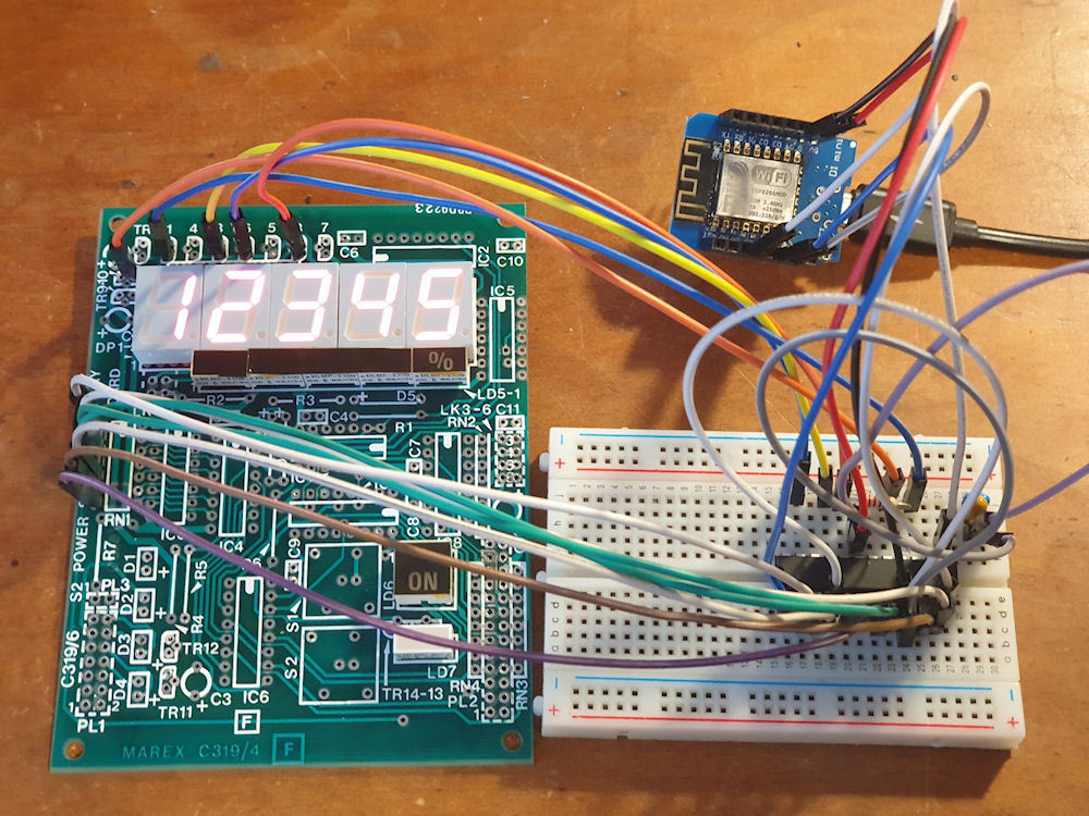
MAX7219 LED controller (for common-cathode LEDs) running common-anode 7 segment displays. The brightness isn't quite what I could like, but it should be fine. I may be able to tweak it a little, but the MAX7219 wasn't really designed for running common-anode, so if not, I can't complain.
Now to make up a little daughter board with the MAX7219 and try it out for fitment/space etc. If all is good, then I'll make some more and get the display boards retrofitted with the new controllers. This IC will daisy chain too, but I might have to get a little clever with the code as this is just addressing the SPI bus directly. It's not using any specific library. Should be doable though, and maybe with some more clever programming I might be able to daisy chain the wind direction indicator onto that. That would be ideal, and then use an ESP32 to run the displays and all of the individual LEDS. Of course, since I am only using 5 of 8 digits, I may be able to use the spare digits for the individual LEDs. Which ever way it works out, I'm super pleased I managed to get the original 7 segment LEDs working. 😊
Update #5.1
More progress! 😀
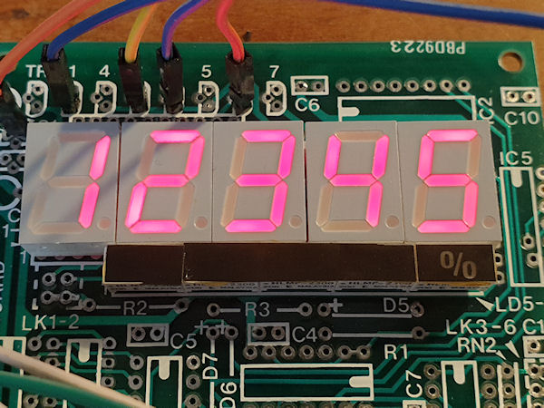
Yes! They can be daisy chained! Each display has to be selected using the chip select pin so a small for loop will cycle through each display, select it and write the numbers to it. That is really good news as it means I will use less MCUs for the display. It may even be possible to get everything running on one ESP32. I'm using an ESP8266 right now just for testing.
What you can see in the video (but too fast to see with the human eye) is the right display is selected and written to, then the left display is selected and written to, and then it loops around. The numbers are just random numbers. Each one generated for each display, each cycle.
Update #5.2
I haven't done a single thing with the ESP32 or firmware for a bit as I have been concentrating on other parts of the system.
I have managed to get the LED display to display decimal floats.
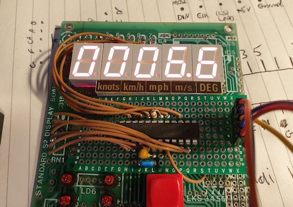
The decimal moves and the numbers shift to the right accordingly, but it is being a proper arse and I cant get it to clear the leading zeros. I mean, I can, but only one leading zero. It does the strangest thing and if there is only one leading zero it will clear that fine, but if there are two leading zeros the very first one will display but not the second. If there are three leading zeros it will display two zeros. 0123.4 displays 123.4 great, but 0012.3 displays as 0 12.3 and 0001.2 displays as 00 1.2. Grrrr. I don't understand why this is happening, although I don't fully understand the original code which doesn't help. I've tried three different ways of clearing the leading zeros and all exhibit the same output. Aside from that it is working great and I should be able to daisy chain all of the numeric displays together, but I have to fix this leading zero issue or it will bug me for eternity!
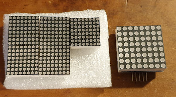
I have been playing about with some LED matrices and I will probably incorporate some on the Marex display. There are one and a half sections of display that are unused. They have no markings and sparse LEDs on the PCB behind so are useless as is. A 3mm LED 8x8 matrix fits perfectly in one half of a display section (as shown in a previous picture with the LED smiley in the bottom left) but doesn't have much resolution. I ordered some 1.9mm LED matrices to have a play with and I can fit six of these making a 24x16 matrix. However the display window is only big enough for 24x12, which should be enough for what I want to do. I was thinking they could be used to display simple images of clouds, or sun, or animated rain. It could show what is happening in real time, or show the forecast, or both. I could have bar graphs or maybe a line chart. Even scrolling text. The single 8x8 is too low resolution really for images, but could display smileys or something similar.
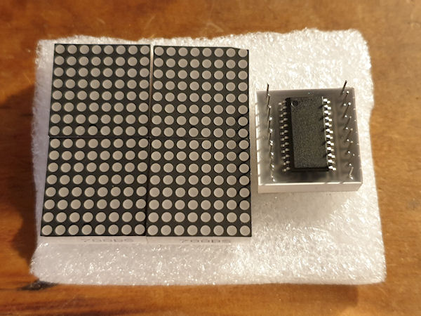
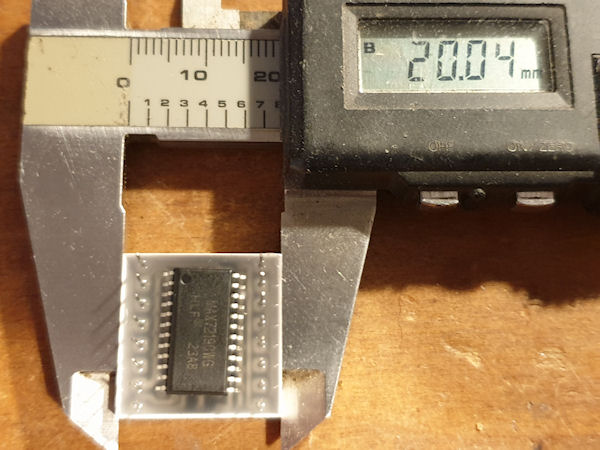
In order to fit the six 1.9mm matrices I'm going to have to solder a MAX7219 IC, dead bug style to the rear of each matrix. I ordered some SMD MAX7219's and they fit fine, but connecting them up will be fiddly. It's either that or a wiring spaghetti. 6x16 wires going to other boards.... Nah... I'll spend my time doing the fiddly stuff.
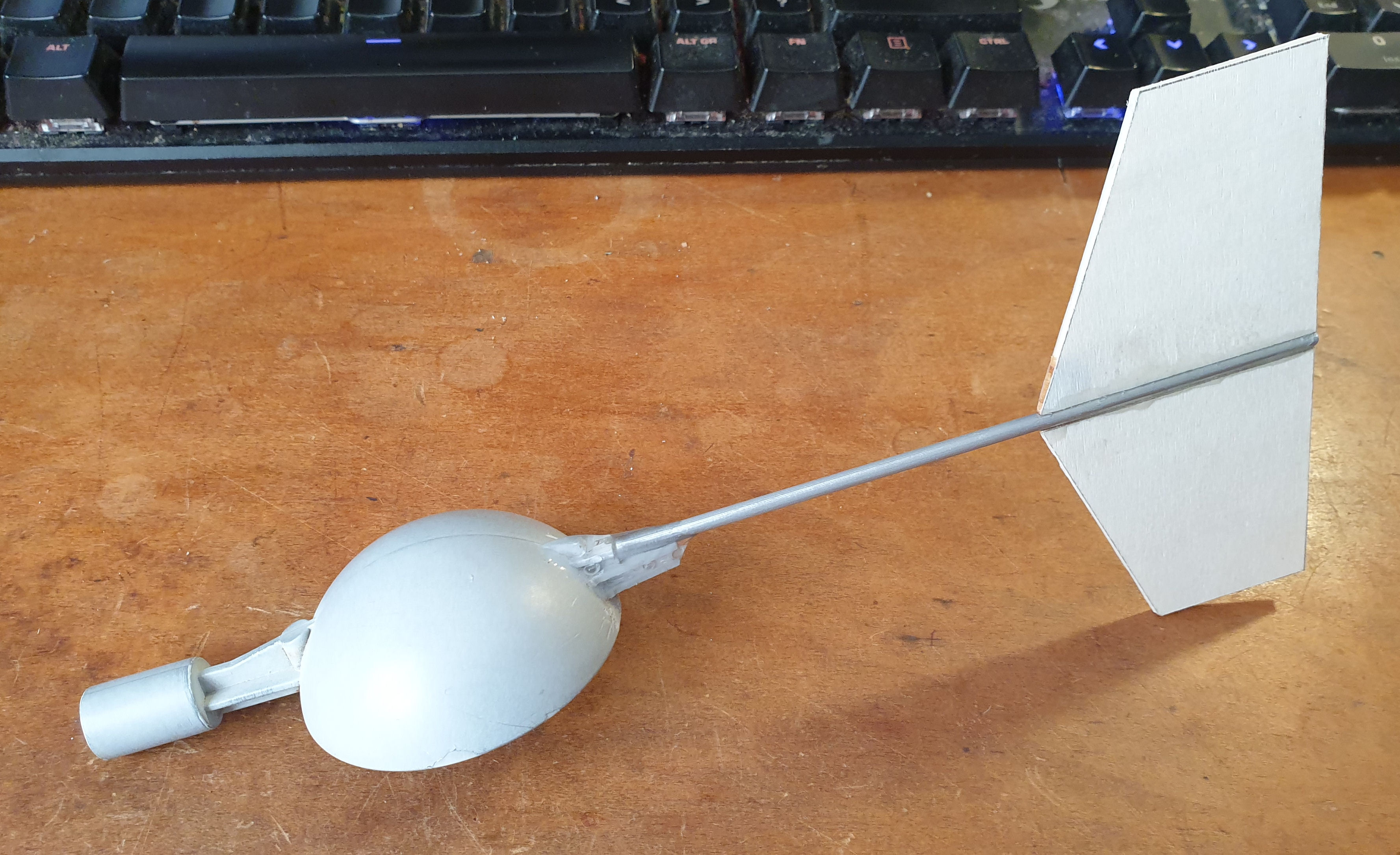
I have mostly rebuilt the wind vane and it has come out pretty good so far. I decided on using some 3mm sheet Basswood as I had some to hand. I'm not too keen on the idea of using wood as the last wood wind vane I built only lasted a couple of years before becoming rotten and falling to bits, even after a few coats of white car paint. This time I have coated the Basswood with a clear UV activated epoxy, as I had some to hand. The first coat soaked into the wood a bit and raised the grain. I applied a liberal second coat and that has cured very nicely leaving a smooth finish. I'm not too fussed about the looks of the thing as it can't be seen close up when installed in place, so looks matter little. My aim it to protect it from the elements and with a few coats of paint it should fair well, hopefully! If not, I have found some carbon fibre sheet that will probably work, but it's not cheap and I am trying to do this project as cheaply as possible. Most cost so far has been on the electronics top get the Marex display working. The weight of the new tail on the wind vane is much much better than before. The whole thing (pictured above) weighs in at 26.5 grams without counterweight. Just the old 3D printed tail alone weighs 28 grams so a big improvement. The lighter tail means a lighter counterweight at the nose, so the whole thing will be considerably lighter. This may help give a better wind direction as too much weight causes too much inertia and the vane wants to spin around, or keep swinging left to right and vice versa. I'm not getting my hopes up too much with it though as the wind vane's placement on top of my workshop gets some pretty dirty wind and seems to come from all directions.
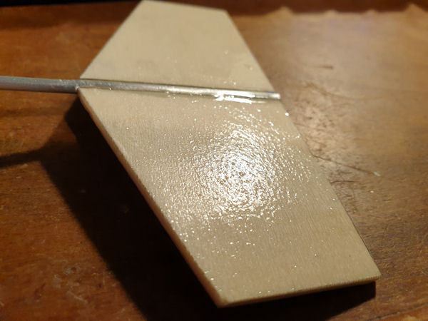 One coat of epoxy.
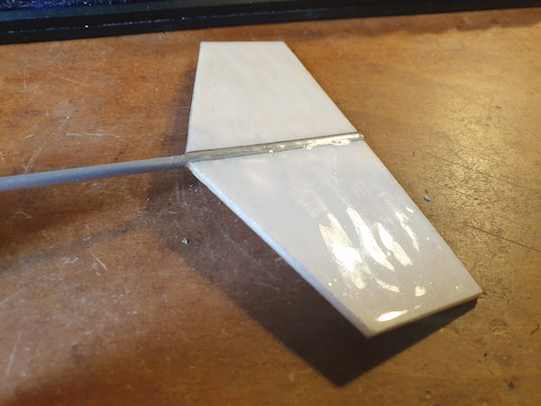 Two coats of epoxy.
There is still much to do but once the sensors (wind/rain etc) are fixed and working I can get the station outside and up and running, then concentrate on the display, database and web front end, and phone front end if I decide to do so. I have also seen a really neat ESP32 e-paper weather station display that I may be able to get to work with this. That would make a really nice display for my desk.
There is also a lot of work to do with regards to storing records - daily, weekly, yearly minimums and maximums. As the main weather station ESP32 will be crunching all the numbers and storing them on an SD card it is going to be a lot of programming for the ESP, but once done should offer a really feature rich weather station. I'm also toying with the idea of using some GPIOs to drive external things such as alarms or automation. A while back I saw a motorized sun shade that had an anemometer wired to it. The anemometer was to make the shade retract automatically if the wind went over a certain speed. Similar things could be done using GPIOs and external relays, or whatever.
I fell across a very neat hall effect sensor, whilst looking at hall effect sensors, surprisingly!
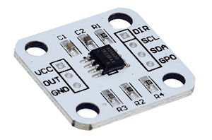
The AS5600 is a 12bit rotary angle position sensor. Its one small IC that will read the angle of a magnet above it. Using one of these and a round diametric magnet I should be able to read the wind vane angle to 12 bits. Currently it uses just eight reed switches so only has the ability to show eight wind directions. Using the AS5600 I should be able to read the wind direction down to a quarter of a degree, or maybe half a degree. One whole degree is enough for me. Going from 8 to 360 positions is more than enough! I would have to modify the way the wind vane works as it would require a shaft to go down into the case, right above the AS5600 where the magnet would be. Doing this would allow me to use (I would have to) a larger bearing, something along the lines of a roller skate bearing, which would give better stability and maybe longevity. I have ordered the AS5600 and some magnets to have a play with and see if it is viable, and I think it will be.
That's about it for now. Until the next update.
Archived from radmon.org - originally posted 12/05/2024
Add Comment
This policy contains information about your privacy. By posting, you are declaring that you understand this policy:
- Your name, rating, website address, town, country, state and comment will be publicly displayed if entered.
- Aside from the data entered into these form fields, other stored data about your comment will include:
- Your IP address (not displayed)
- The time/date of your submission (displayed)
- Your email address will not be shared. It is collected for only two reasons:
- Administrative purposes, should a need to contact you arise.
- To inform you of new comments, should you subscribe to receive notifications.
- A cookie may be set on your computer. This is used to remember your inputs. It will expire by itself.
This policy is subject to change at any time and without notice.
These terms and conditions contain rules about posting comments. By submitting a comment, you agree with these rules:
- Although the administrator will attempt to moderate comments, not all comments can be moderated at all times.
- You acknowledge that all comments express the opinions of the original author and not those of the administrator.
- You will not post material which is knowingly false, obscene, hateful, threatening, harassing or invasive of privacy.
- The administrator has the right to edit, move or remove any comment for any reason and without notice.
Failure to comply with these rules may result in being banned from submitting further comments.
These terms and conditions are subject to change at any time and without notice.
Comments