- Posted on
- Featured Image
-
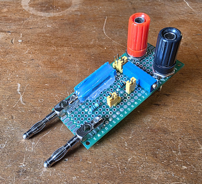
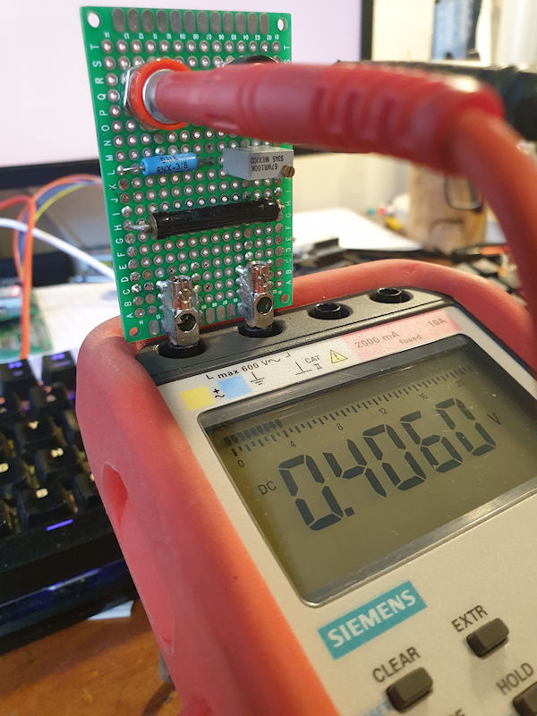
I recently got a new multimeter that has a slightly higher burden than the meter I was previously using. This meant that the original voltage divider I made wouldn't calibrate to my new meter. The solution was to increase the resistance of R2 in the divider. On the v1 divider R2 was made up of a 1MΩ and a 100KΩ trimmer pot in series. To increase the R2 in the v2 divider I added a couple of 100KΩ resistors in series with the 100KΩ trimmer pot. R2 became 1MΩ + 100KΩ + 100KΩ + 100KΩ (pot) all in series. I added two jumpers alongside the two new 100KΩ resistors so I can put them in circuit or