- Posted on
- • Geiger Counters
AEGTest Hound-3699 Radon Monitor - Pt.1 Review and Teardown
- Author
-
-

- User
- Mr Blinky
- Posts by this author
- Posts by this author
-
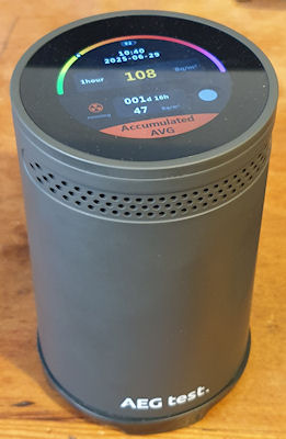
AEGTest Hound-3699 Radon Monitor Review & Teardown
Many high resolution images of the teardown are here.
I have been getting to know Radon quite a bit more of late. I manage a couple of sites at work and these are in Radon areas. I have used the Airthings Corentium and also fitted an Airthings View Radon 2989 in the basement of one of the sites. Monitoring is ongoing. I have also been experimenting with Radon a little too – discovering it’s progeny. I have also discovered that many (all?) of my U-238 sources also emit small amounts of Radon, local to their storage and I want to keep an eye on that, so I bought myself a Radon monitor – a AEGTest Hound-3699.
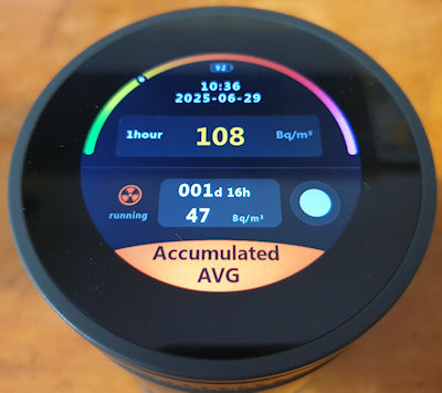
All in all it’s not a bad unit. £120 shipped from the jungle site. I like the screen and the touch on it is very nice. You can use quick light touches, just like a mobile phone, and it is fast to react. The up/down selections are a bit clunky though. It is fairly easy to use and a neat feature is it will automatically generate PDF reports – Set it up, let it run, plug into PC, Looks like a USB stick, grab PDF, put back in service. It is quite a neat feature. A sample report PDF is attached below. I was going to do a bit of a review on it, maybe a look inside, but when I came to make a copy of the manual (there is no electronic version available) I noticed it said “Any unauthorized copying or reproduction of this manual is strictly prohibited without prior written permission from AEG test.” Like, WTF? It’s a manual. They should be free for all. It is no good without the product, but may help someone actually purchase the correct product if the manual is available without purchasing the product itself.
I really dislike that kind of thing. So I scoured the manual (and the box, and the device) (which sadly I can’t copy and upload here) and looked for everything else it said I can’t do — and guess what? Nothing.
It doesn’t say I can’t tear it down.
It doesn’t say I can’t identify the parts.
It doesn’t say I can’t reverse engineer sections to see how it ticks.
It doesn’t say I can’t probe the circuits to trace where the data flows.
So I'm going to do all of that. Every bit of it. ALL OF IT. 🤣
The following is a detailed teardown, IC identification and a brief reverse engineering. The following post will be about gaining access to the locked ‘Admin’ menu (that they don’t want you in too, but they didn’t say I can't break in!). Then hopefully soon a modification to enable this little puppy to talk to the internet. If the manufacturer won’t let me do X, I will most certainly do Y and Z. They can bite my shiny metal ass.
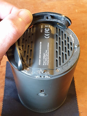
First off is getting into the bugger. They don’t really want you inside this thing. The case is clipped together at the sides, with two screws at the bottom under a rubber-baby-buggy-bumper that is glued in place. I’m guessing a line between not letting anyone inside and keeping the unit serviceable. A bit too much brute force could rip of destroy the rubber-baby-buggy-bumper. I had to tease it off very gently using a flat screwdriver, lots of force and a bit of time. Eventually I had gotten enough of it back without breaking anything and revealed the two screws. Take out the two screws then crack it open by squeezing it, and use a spudger to pop open the clips – two each side. After disassembling and reassembling a few times, it becomes quite easy to just squeeze in the right place to pop it open. Once a couple of clips are free it is much easier.
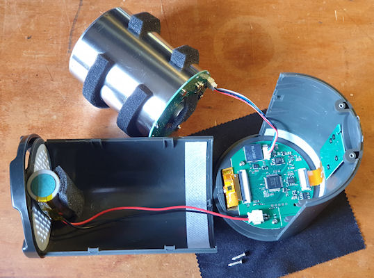
After opening it comes apart into three pieces – two halves of the case and the ionization chamber. The chamber is connected to the mainboard with a small JST connector. It has a squeezy lever to unlock the connector and it will disconnect fairly easily. The battery is also connected to the mainboard and it would be prudent to disconnect the battery and put to one side if playing about with the insides of the unit, unless you needed it powered on. Those INR21700 batteries can give out a huge amount of current – so don’t short it or you will have a really bad day.
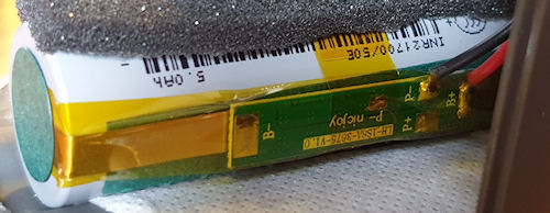
The battery is (by the looks of it) a genuine Samsung INR21700/50E, the specifications are:
- Model: INR21700-50E
- Size: 21700 (21mm x 700mm)
- Head type (Positive terminal): Flat Top
- Maximum Capacity: 5000mAh
- Typical Capacity: 4900mAh (0.2C discharge)
- Peak discharge rating: 15A
- Continuous discharge Rating: 9.8A
- Nominal voltage: 3.6V
- End-of-charge voltage: 4.20V
- End-of-discharge Voltage: 2.50V
- Rechargeable: Yes
- Protection circuit: Unprotected
- Approximate Dimensions: 21mm x 70mm
- Approximate Weight: 68g
It’s a decent battery and has a protection board mounted on the battery itself.
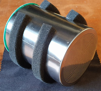
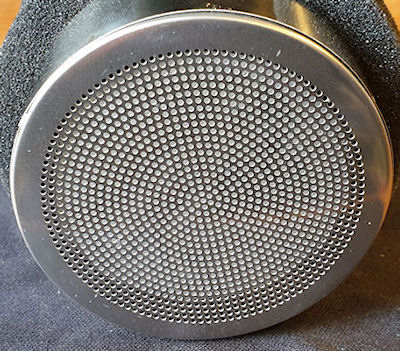
Now the chamber. Not particularly unusual to me. It isn’t dissimilar to ion-chamber radiation meters such as the CDV-715. This works on a pulsed output, much like GM tubes, so should be fairly easy to mod. The chamber is open to the air but I am unsure of the exact mode of operation. I have a feeling that some kind of charge accumulates, and then when it gets so much, it ionizes and creates a pulse. I have had some quite strange effects with it either not counting or counting too much, but generally when I ground myself and the chamber whilst reassembling this reduces funniness a lot.
 The chamber measurements:
- Diameter - 65mm
- Chamber length - 78.5mm
- Length including PCB - 81mm
- Overall length including metal rear cap - 85.2mm
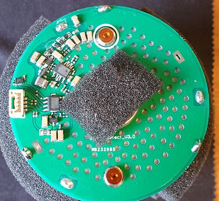
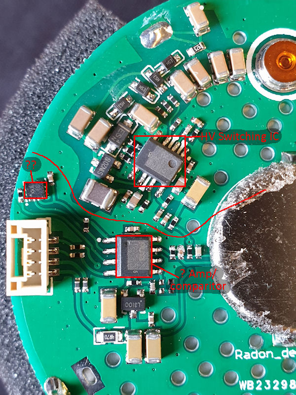
This is the PCB on the rear of the chamber. The top part is the HV stage and the lower part is the detection/pulse stage. There is an unknown IC that neither I nor ChatGPT can find. I think it may be a stable voltage reference for the pulse – I could be wrong. The other two SOP-8s have had their markings removed. The one at the top in the HV stage is probably a switching IC as it has an inductor to its lower left and some hefty caps. The other SOP-8 is either an amp or comparator, or something similar. The tiny IC is quite unknown. Looking at the connector it’s pins (going from top to bottom) are as follows:
- Pulse out (held high to +3V, drops to ~0.2V on pulse)
- Reference voltage?
- Ground
- +V
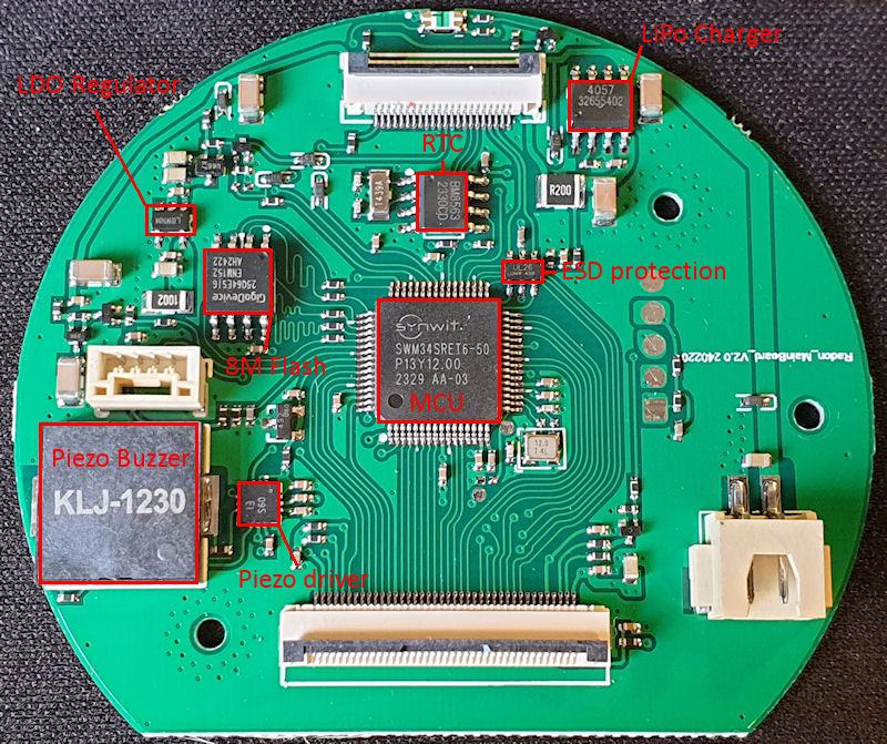
The mainboard has a few bits and pieces on it (datasheets linked below). Right at the top is the indicator LEDs (reversed). The MCU is a SWM34SRET6 (ARM Cortex M33). We also have an RTC above the MCU, some ESD protection on the SPI/I2C USB lines. Over at the top left an LDO regulator and just under that to the right is an 8M flash IC – It probably stores the PDF on that. The big thing at the bottom left is a Piezo buzzer for the bleeps and alarms, and to the right of that is a driver IC for the buzzer.
The rear of the mainboard is boring.
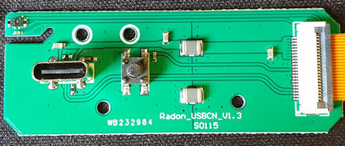
The USB port and power switch PCB. This just has the USB C connector, power button but also a sneaky hidden sensor. The sensor is a temperature and humidity sensor – but the manufacturers don’t have that displayed at all, and I think I know why. At first I had trouble identifying it so ChatGPT helped. It looks just like a SHT30-DIS (or similar) so I think this may be a copy of the SHT30-DIS (or similar) and because of that they are not including the readings. It shows in the report PDF two fields – Temperature alarm and Humidity alarm, and both show ‘not support’.
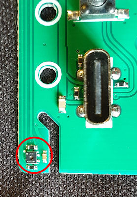
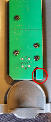
You can see the sensor a little more clearly in the above image. There is a cut-away in the PCB to help insulate the sensor from the rest of the board. The sensor is also mounted very close to the battery, so it may be used for monitoring battery temp, and as this will change during charging so that might be another reason they are not showing the values.
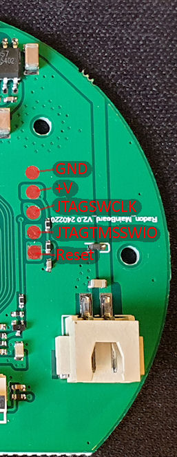
The last bit is the JTAG header pins on the board. And they are, just that.
And that just about wraps this up. Next post will be accessing the ‘Admin’ menu, and if I can manage to get my mod working properly, I’ll certainly post about that.
Download a sample PDF report from this monitor here.
Datasheets for the ICs:
https://www.onsemi.cn/download/data-sheet/pdf/ncp585-d.pdf
https://www.digikey.com/en/products/detail/evvo/TP4057/22482076
https://mm.digikey.com/Volume0/opasdata/d220001/medias/docus/5010/TP4057.pdf
https://www.makerguides.com/wp-content/uploads/2025/01/BM8563-datasheet.pdf
https://datasheet.lcsc.com/lcsc/2108131930_TECH-PUBLIC-TPUSBLC6-2SC6_C558442.pdf
Archived from radmon.org - originally posted 29/06/2025
Add Comment
This policy contains information about your privacy. By posting, you are declaring that you understand this policy:
- Your name, rating, website address, town, country, state and comment will be publicly displayed if entered.
- Aside from the data entered into these form fields, other stored data about your comment will include:
- Your IP address (not displayed)
- The time/date of your submission (displayed)
- Your email address will not be shared. It is collected for only two reasons:
- Administrative purposes, should a need to contact you arise.
- To inform you of new comments, should you subscribe to receive notifications.
- A cookie may be set on your computer. This is used to remember your inputs. It will expire by itself.
This policy is subject to change at any time and without notice.
These terms and conditions contain rules about posting comments. By submitting a comment, you agree with these rules:
- Although the administrator will attempt to moderate comments, not all comments can be moderated at all times.
- You acknowledge that all comments express the opinions of the original author and not those of the administrator.
- You will not post material which is knowingly false, obscene, hateful, threatening, harassing or invasive of privacy.
- The administrator has the right to edit, move or remove any comment for any reason and without notice.
Failure to comply with these rules may result in being banned from submitting further comments.
These terms and conditions are subject to change at any time and without notice.
Comments