- Posted on
- • Geiger Counters
Adding live high voltage reading to the modified GK Radmon Geiger counter
- Author
-
-

- User
- Mr Blinky
- Posts by this author
- Posts by this author
-
Modifying my GK Radmon kit Geiger counter to run ESPGeiger firmware has gained a little interest in it. John (BroHogan) the creator of the GK Radmon and other kit counters caught wind of this and appears very happy for me to be slicing and dicing his work - all in the good spirit of things, and Steadramon, the writer of the ESPGeiger firmware is looking if he can make a drop-in version of his ESPGeiger firmware that can be loaded onto the GK Radmon (and probably GK Radmon Plus too) without the need to modify the counter itself. That would be very cool. It has also spurred on an ESPGeiger build with HV PWM support, and with a bit of luck that should be done in the not too distant future.
As I mentioned in my previous post (here) there is a feature of the ESPGeiger-HW that I didn't implement when I did the original mod. That is live high voltage reading. Long story short, I removed the potentiometer as that wasn't needed anymore and added two resistors to create a voltage divider so ADC0/A0 (the analogue input pin) can handle up to 1000v. Based on a previous project (here) I added a 1 gigaohm and a 1 megaohm resistors to make a 1000:1 voltage divider. 1000v on it's input will give exactly 1v on it's output - perfect for the 0-1.0v input on the ADC pin of the ESP8266.
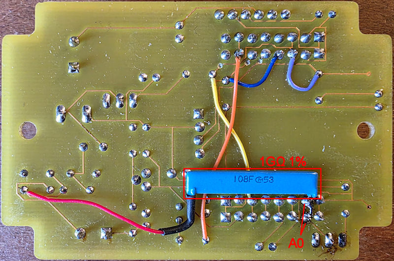
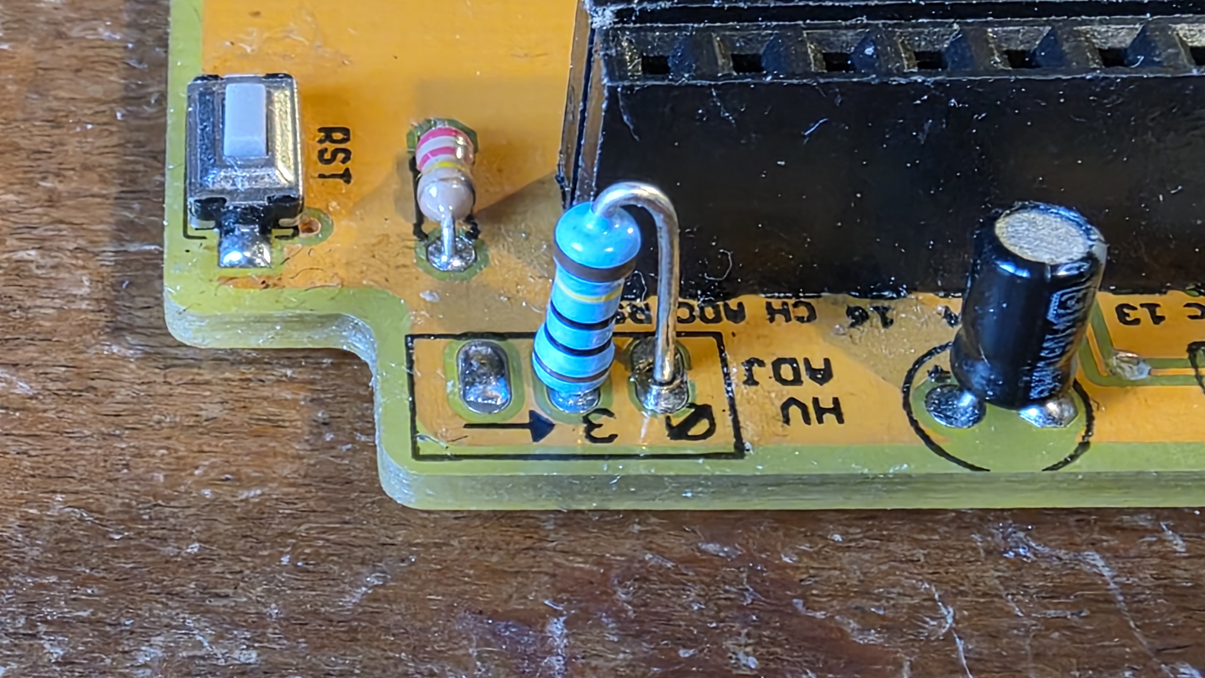
The two images above show where to connect the resistors. I placed one on the top side and the other long flat resistor on the underside of the PCB. Essentially it is the 1G0 between the HV (before the anode resistor) and A0 on the ESP8266, and also the 1M0 between A0 and ground. That's it. A couple of notes on this implementation - this is crude. It has no extra filtering and the additional load (I'll come to that in a minute) on the HV PSU will most likely be causing some ringing, maybe increasing noise into the tube anode, so bear this in mind if you use this kind of modification. The other thing is the HV PSU burden - the additional load on the PSU. Whilst 1 gigaohm (+ 1 megaohm) is a very large resistance, it does bear some burden on the PSU. I have seen this vary from counter to counter. Some counters are simply not affected, others are. This is one that is affected, slightly. Adding in this voltage divider has pulled the HV down by 7~10 volts at around 400v. I see this when I use a 1000:1 divider on my multimeter too. Both dividers in parallel causes a voltage drop of 14~20v so I only kept the meter in circuit for as long as I needed to.
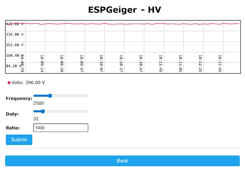
Calibrating the ESPGeiger for the voltage was pretty straight forward. Fire the thing up, add in my meter with 1000:1 divider and measure the voltage, then change the ratio setting in ESPGeiger firmware until the value shown in ESPGeiger is around the same as my meter. Adding in my meter caused a small voltage drop, and I set the voltage the ESP8266 was reading to that of my meter. This way, regardless of whether the voltage has dropped or not, the voltage the ESP is reading is the correct voltage if the same as my meter. Removing my meter causes the voltage to jump up a little, back to 'normal' and this can be seen on the ESPGeiger HV page. Something to note, and can be seen in the video below, is the voltage shown in ESPGeiger isn't quite linear. When set to 400v there is a little drift either side of that. If I set the ratio or 400v, then dropped the duty down for high voltage of say, 200v, the ESPGeiger would be reading a little high, at maybe 210v. The same goes for the high end - at 600v ESPGeiger may report around 580v. It also jumps up and down by a handful of volts each way too. I'd say the ESPGeiger is reading the voltage +-7v when set at 400v. It isn't really good enough to use it as a recorded metric, but does offer a little diagnostic value.
I had a bash at ramping the high voltage up. I reached about 1002v then dropped back as I don't want to damage the counter or ESP8266. That's a testament to John's (BroHogan) design. 1000v (stable) from 3.3v is impressive. I imagine there was probably a bit more noise on the HV at that voltage, but still, it's impressive. The 1002v was at 150 (of 255) duty cycle, so still more room. How much, I can't say as these little boost circuits tent to get their knickers in a twist at high duty cycles, effectively reducing the off time massively. I'm not kitted out for scoping these high voltages, yet. I need to obtain, or make the tools so I can use my scope on the HV output itself, without adding too much more burden to the PSU. A little more burden on a meter is OK, but on a scope may introduce ringing/noise, the stuff we want to see, not add in to the mix - you end up chasing tails that way!
These are the resistors I used for this. Not mega expensive either (except for the shipping ☹️).
- 1G0 - https://www.mouser.co.uk/ProductDetail/580-MHR0424SA108F70
- 1M0 - https://www.mouser.co.uk/ProductDetail/594-MBB02070C1004FCT
I think that's about it for this, so I will leave you with an ultra-boring video showing the high voltage on the ESP8266 and my meter. I do ramp the HV up to 1000v in the video, and it doesn't let out the magic smoke!
Add Comment
This policy contains information about your privacy. By posting, you are declaring that you understand this policy:
- Your name, rating, website address, town, country, state and comment will be publicly displayed if entered.
- Aside from the data entered into these form fields, other stored data about your comment will include:
- Your IP address (not displayed)
- The time/date of your submission (displayed)
- Your email address will not be shared. It is collected for only two reasons:
- Administrative purposes, should a need to contact you arise.
- To inform you of new comments, should you subscribe to receive notifications.
- A cookie may be set on your computer. This is used to remember your inputs. It will expire by itself.
This policy is subject to change at any time and without notice.
These terms and conditions contain rules about posting comments. By submitting a comment, you agree with these rules:
- Although the administrator will attempt to moderate comments, not all comments can be moderated at all times.
- You acknowledge that all comments express the opinions of the original author and not those of the administrator.
- You will not post material which is knowingly false, obscene, hateful, threatening, harassing or invasive of privacy.
- The administrator has the right to edit, move or remove any comment for any reason and without notice.
Failure to comply with these rules may result in being banned from submitting further comments.
These terms and conditions are subject to change at any time and without notice.
Comments