- Posted on
- • Geiger Counters
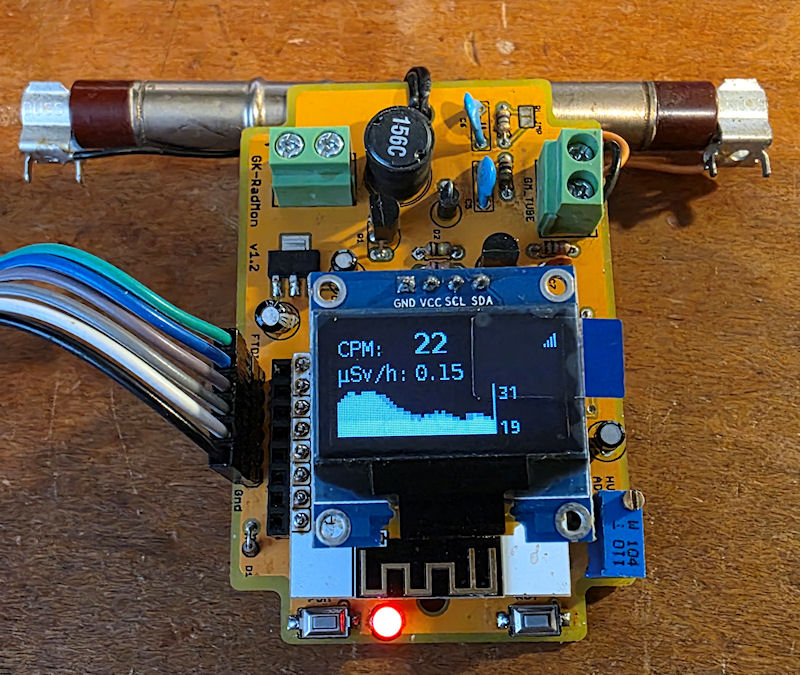
Modifying the GK Radmon Geiger counter to run ESPGeiger firmware
- Author
-
-

- User
- Mr Blinky
- Posts by this author
- Posts by this author
-
Please note that this mod is no longer necessary as the pins can be selected within the ESPGeiger firmware settings.
A couple of days ago Steadramon released an updated version of his ESPGeiger firmware, which included a new webhook feature I had been patiently waiting for. This got me playing about with ESPGeiger again and the thought crossed my mind "can I get it to run on my GK Radmon?" I bought my GK Radmon kit about five years back. I didn't like the original firmware much. Not that it was bad, it just didn't suit the way I use my counters. The original firmware was written for very low power consumption, power saving and sleeping. It would wake up every five minutes, run for thirty seconds (IIRC), send the reading to radmon.org, and then go back to sleep again. I wanted an always on, always counting, submitting every 60 seconds type counter, so I rolled my own firmware, and it sat like that for a few years.
I have used ESPGeiger firmware for a good couple of years now, and also helping Steadramon with his ESPGeiger HW Geiger counter, I have a pretty good knowledge of it. Not so much the code, but the hardware. Thinking about it, it should work. We need SDA, SCL for the OLED, the LED pin and the HV PWM out to the HV PSU. And maybe a button, but I am omitting the button for now as I don't really use it. As the HV PSU is driven in exactly the same way as the ESPGeiger HW, then with some pin swapping, it should literally drop in. So I set to work.
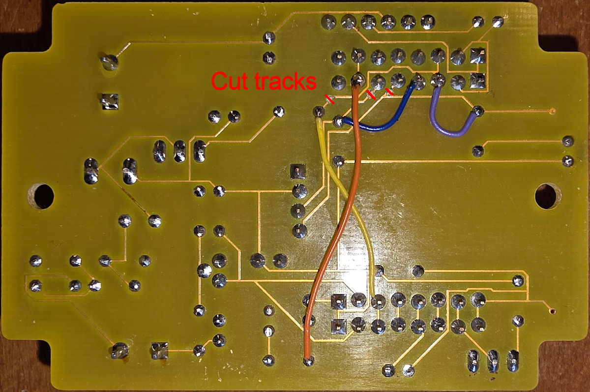
First after identifying the relevant pins we need to cut four tracks. On the bottom side of the board SCL, SDA and the HV PWM tracks need to be cut, as close to the ESP8266 as possible. In cutting the SCL and SDA tracks right next to the pin header, this retains the function of the RDY LED, and acts as a heartbeat of sorts as it will flash every time the OLED is updated.
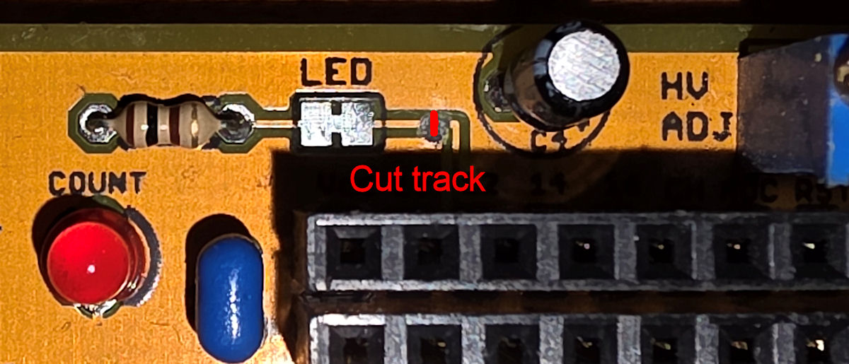
There is also the LED track to cut on the top side of the board.
After cutting the tracks four wires need soldering in place as shown in the image above. The pins to change are these:
GK Radmon FW        → ESPGeiger HW FW

HV PSU PWM GPIO5    → GPIO12
OLED SCL GPIO2      → GPIO4
OLED SDA GPIO0      → GPIO5
LED GPIO12          → GPIO15
Once the modification to the board has been done, it can be reassembled (plug in ESP8266, OLED), but leave the GM tube out for now to test the HV PSU function and it's voltage, that is after flashing the ESP8266 with the ESPGeiger HW firmware. This version, as far as I know, is the only version of ESPGeiger firmware that has PWM HV control. The HV PSU on both the ESPGeiger HW and the GK Radmon are the same principle - a simple PWM driven boost circuit. A PWM signal from the ESP8266 drives the boost circuit and the voltage is dependant upon it's frequency and duty cycle, and the components used. As the principle is the same then the ESPGeiger firmware should run the GK Radmon HV PSU without issue.
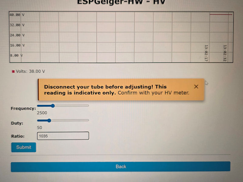
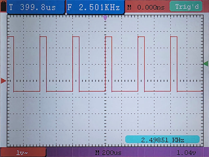
After flashing the (GK Radmon) ESP8266 with the ESPGeiger HW firmware I checked set the frequency to 2.5 KHz as noted in the GK Radmon documentation, and I set the duty to 50 (of 255 / around 20%) for now. Then I connected my oscilloscope and checked the PWM signal -it's clean:
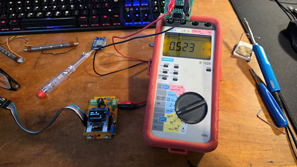
Then I checked the voltage using my trusty 1000:1 voltage divider and it was a little high at ~525 V:
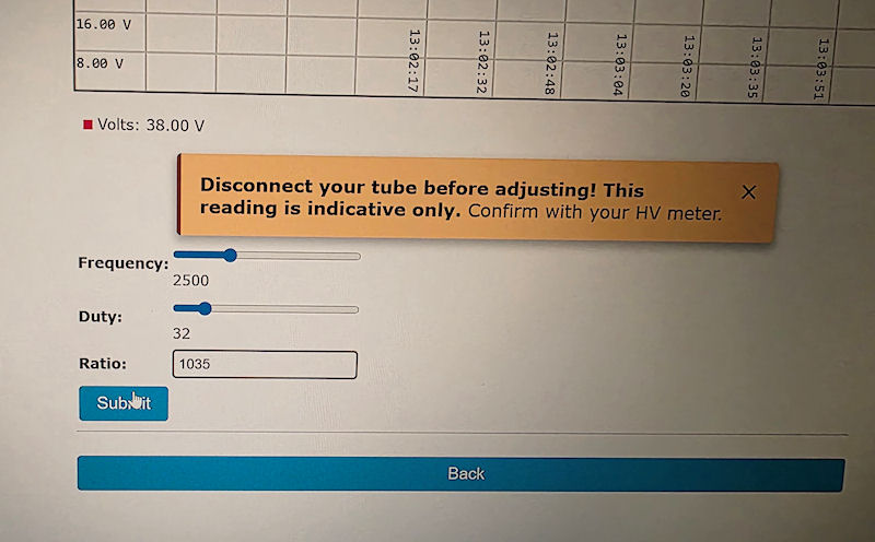
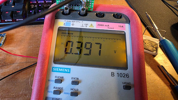
After a little trial and error I got a nice stable ~398 V with a frequency of 2.5 KHZ (as per GK Radmon spec) and a duty cycle of 32. It seems very stable too.
After leaving for a short while the voltage seemed quite stable so I connected up the GM tube and configured ESPGeiger to submit to radmon.org, MQTT (Home Assistant) and the new webhook feature. Something to note: the ESPGeiger HW has a feature that I haven't implemented on this GK Radmon yet - live high voltage reading from the HV PSU. This would require recalculating and changing the resistor values to drop the HV to something more suitable for the analogue input of the ESP8266. The basic ESP8266 module has a voltage range of 0-1 V on A0, whereas the Wemos D1 Mini has a voltage range of 0-3.3 V as the Wemos D1 Mini incorporates an additional voltage divider on it's board, so the values would need to be changed to ensure no more than 1 V is seen on A0 of the ESP8266 module. Using the same values that are on the ESPGeiger HW board will most likely result in destroying the ESP8266 module. And even with the correct resistor values, I don't know if it would affect the HV PSU on the GK Radmon. The ESPGeiger HW was designed with the live voltage reading in mind, the GK Radmon was not.
For now though, with or without the live HV reading, the ESPGeiger firmware has given this counter a new lease of life! 😊
Add Comment
This policy contains information about your privacy. By posting, you are declaring that you understand this policy:
- Your name, rating, website address, town, country, state and comment will be publicly displayed if entered.
- Aside from the data entered into these form fields, other stored data about your comment will include:
- Your IP address (not displayed)
- The time/date of your submission (displayed)
- Your email address will not be shared. It is collected for only two reasons:
- Administrative purposes, should a need to contact you arise.
- To inform you of new comments, should you subscribe to receive notifications.
- A cookie may be set on your computer. This is used to remember your inputs. It will expire by itself.
This policy is subject to change at any time and without notice.
These terms and conditions contain rules about posting comments. By submitting a comment, you agree with these rules:
- Although the administrator will attempt to moderate comments, not all comments can be moderated at all times.
- You acknowledge that all comments express the opinions of the original author and not those of the administrator.
- You will not post material which is knowingly false, obscene, hateful, threatening, harassing or invasive of privacy.
- The administrator has the right to edit, move or remove any comment for any reason and without notice.
Failure to comply with these rules may result in being banned from submitting further comments.
These terms and conditions are subject to change at any time and without notice.
Comments (2)
Very nice to see! As I just wrote Paul - It's always a pleasure to see improvements and adaptations to what I have built.
As you mentioned the original SW was meant to save power when the device was solar powered.
Looking forward to learning about your adaptation and improvements.
All the best with your projects.
John (AKA BroHogan)
It's very nice to hear from you, John, and thank you for your kind comment. The GK Radmon has always been a good counter for me. Never really hiccupped at all. It has been running solid since I got it and put it together. It is station 'radspod_two' on radmon.org.
I too have been speaking with Paul and I left him some info on the GK Radmon on his github page as he may be able to write a drop-in firmware that utilizes the original pins, which would mean I would have to un-mod my mod, but hey, if a step back moves things forward, I'm happy to.
Again, nice to hear from you and all the best.