- Posted on
- • Geiger Counters
A little gem - The Yaorea YRG01 Pt.3 - Improving the mod - Now with Blue blinky LED!
- Author
-
-
- User
- Mr Blinky
- Posts by this author
- Posts by this author
-
I have a few of these little counters on hand and decided to mod a few. One I have at my office sat on my desk, and another two I'll be sending out in the wild. My original intention was to mod a bunch of them and sell them to potential radmon.org users as a 'works right out of the box' counter submitting to radmon.org. I changed my mind after realizing they take a lot longer to actually mod than I initially thought (because I'm doing a much better job on these than the first), and that recently a version of ESPGeiger firmware was released with a bug that made them unable to update over-the-air. The fix involved stripping down a couple of counters and updating by USB. They got fixed, but took a little work. Steadramon quickly fixed the issue, but as I was updating sometimes two or three times a day with consecutive updates, I got caught out. No biggie, and I doubt it will happen again. But you never know, so I'll be a bit more cautious next time.
It was that not being able to update thing that really drove the nail in the coffin. No way could I get a counter out to people, with little knowledge of ESP's/programming and such, and have them brick, or not update, or anything. The user wouldn't have much of an idea so they would have to be shipped back and so on. And for the amount of money involved, nah, I'll leave it.
So I have decided to still mod these at my convenience, and just give them away to people I know. And because I am giving them away, I have improved the mod. Mainly the quality of the mod install, but I have also added another wire to connect the blue LED on the front panel to the ESP-12F so it blinks with tube activity. I removed the redundant(?) BLE IC completely this time. The ESP still turns on and off by selecting 'BLE - On/Off' in the menu.
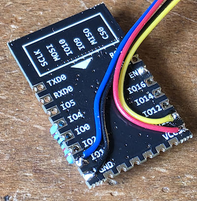
First thing was to just solder some flying leads and the two 10K resistors on to the ESP-12F module. I bought some better wire for this. It is 30AWG wrapping wire, and is well suited to this kind of mod. 4 wires soldered on then held in place with some hot glue. Don't forget to program the ESP-12F before adding the wires and resistors as your programmer might not like them. Program the untouched module before doing anything and verify it is working, WiFi works and you can connect it and view it on your network.
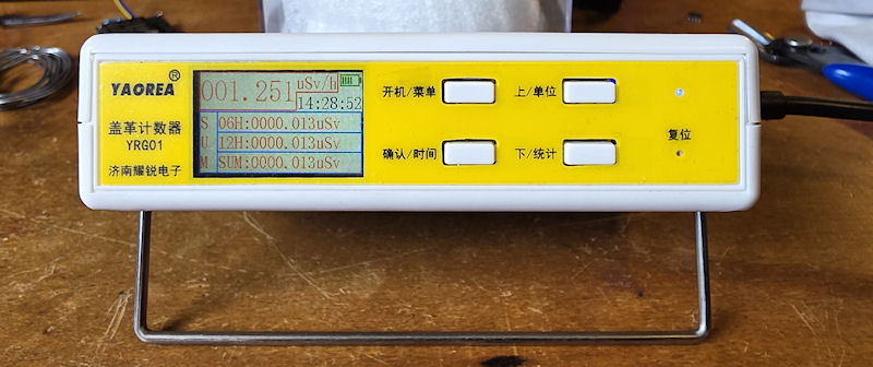
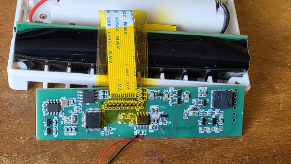
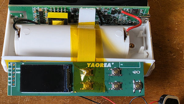
Next pop open the YRG01. Pull the front panel PCB and first, before anything, support the ribbon cable with some Kapton tape. Both sides. The ribbon cable is fragile and poorly executed in this manner. This kind of ribbon should be socketed, not soldered. Copper work hardens, so moving it back and forth will eventually break the conductors, so I tape it in place whilst working on the unit. When I'm finished and reassembling, I remove the front piece of tape from the PCB, just up to the ribbon cable, and then let the ribbon fold back a little and reapply the tape. This stops it being in too much of an upward direction when reassembling. I cut out a little bit where the pulse wire will be soldered to the board.
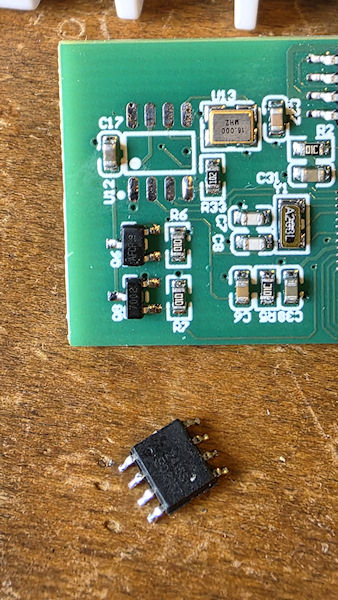
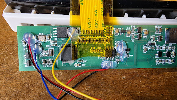
Next was to remove the BLE IC and clean up the pads. Add a drop if solder ready to solder the wires in place.
Then simply solder the wires in place. I have covered this already in part 2, but in a nutshell, we take +3.3v and ground, and the LED wire (blue wire in this case) and solder them in place of the BLE IC. Pin 4 of the IC pads is the front panel LED and suitable resistor. The pulse wire (yellow) gets soldered on to the MCU side of L12. Check my previous post on this mod for more info.
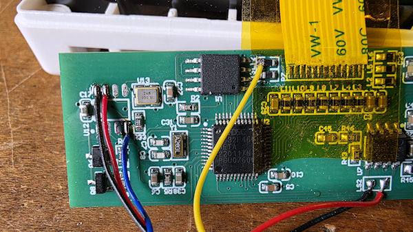
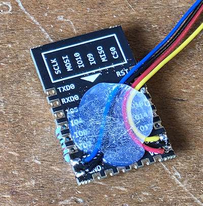
And secure them with some hot glue.
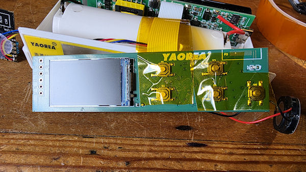
Then it is time to reassemble. I put another piece of tape over the buttons. It probably doesn't do much, but I like the idea it takes up a bit of play behind the front panel plastic buttons.
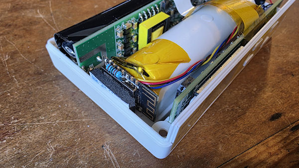
Finally I added a little double-sided sticky foam to the ESP-12F, but left the backing on. The ESP slides between the battery holder and the inside of the case with a nice snug friction fit. I twisted the wires around and they form a nice little loom right to the front panel PCB. And another piece of Kapton tape over the negative battery holder terminal. Pop the lid back on and fire it up!
There are some Hi-Res images of the above and more, here.
Add Comment
This policy contains information about your privacy. By posting, you are declaring that you understand this policy:
- Your name, rating, website address, town, country, state and comment will be publicly displayed if entered.
- Aside from the data entered into these form fields, other stored data about your comment will include:
- Your IP address (not displayed)
- The time/date of your submission (displayed)
- Your email address will not be shared. It is collected for only two reasons:
- Administrative purposes, should a need to contact you arise.
- To inform you of new comments, should you subscribe to receive notifications.
- A cookie may be set on your computer. This is used to remember your inputs. It will expire by itself.
This policy is subject to change at any time and without notice.
These terms and conditions contain rules about posting comments. By submitting a comment, you agree with these rules:
- Although the administrator will attempt to moderate comments, not all comments can be moderated at all times.
- You acknowledge that all comments express the opinions of the original author and not those of the administrator.
- You will not post material which is knowingly false, obscene, hateful, threatening, harassing or invasive of privacy.
- The administrator has the right to edit, move or remove any comment for any reason and without notice.
Failure to comply with these rules may result in being banned from submitting further comments.
These terms and conditions are subject to change at any time and without notice.
Comments