
- Posted on
- • Other Electronics
Voltage divider with calibration V2 - for measuring Geiger counter high voltage
- Author
-
-

- User
- Mr Blinky
- Posts by this author
- Posts by this author
-
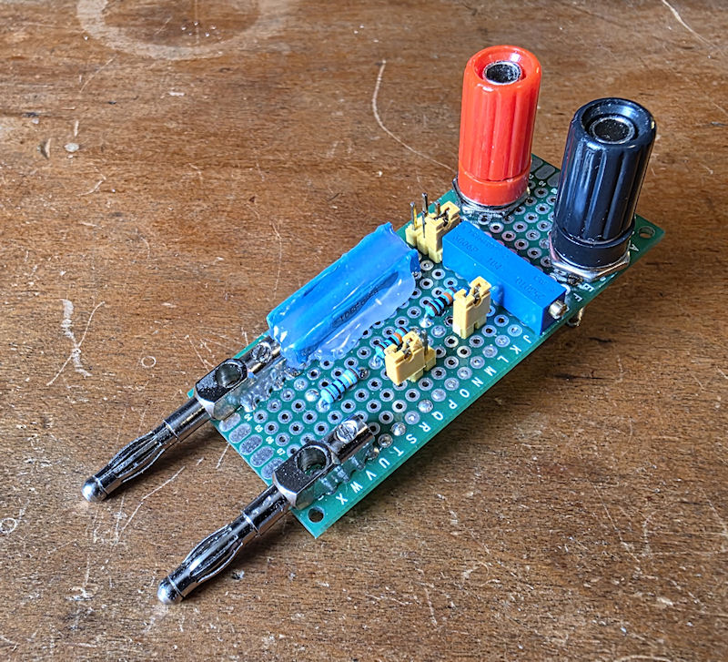
I recently got a new multimeter that has a slightly higher burden than the meter I was previously using. This meant that the original voltage divider I made wouldn't calibrate to my new meter. The solution was to increase the resistance of R2 in the divider.
On the v1 divider R2 was made up of a 1MΩ and a 100KΩ trimmer pot in series. To increase the R2 in the v2 divider I added a couple of 100KΩ resistors in series with the 100KΩ trimmer pot. R2 became 1MΩ + 100KΩ + 100KΩ + 100KΩ (pot) all in series. I added two jumpers alongside the two new 100KΩ resistors so I can put them in circuit or remove them from circuit to suit a wide range of multimeters. I figure I should be able to use a meter with an internal resistance as low as 5, or 6MΩ.
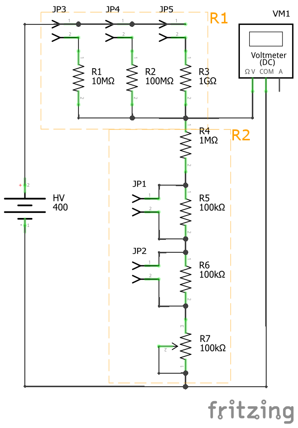
I have had it on the cards for some time to make a new voltage divider that was multifunctional and could cover various ranges, so I took this opportunity to do so. Instead of just having one R1 (1GΩ in the v1) I decided to include three R1's. A 10MΩ, 100MΩ and 1GΩ. I added a small header and I can select any one of the three resistors by moving a jumper. This enables me to use this as a 10:1, 100:1 and 1000:1.
The resistors I used are rated for in excess of 7000V, however due to the construction and placement of components and the board used, the chances for creepage are high at high voltages. I wouldn't normally use this past 1000V, though I may push it on occasion. It's not a product, just a homebrew tool that makes certain jobs much easier, and accurate.
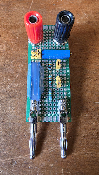
The construction is about as simple as the pictures show. I did run solid core wire for all traces on the PCB bottom and soldered to every via on their way. It helps a little to keep resistances as low as possible, but probably not needed with this. When handling the unit, plugging in, unplugging etc, I kept bending the long thin resistors in towards the middle of the board. I added some hot glue to keep them tight in place. Nothing to do with insulation or anything, just to support the resistors.
I write this about a month after knocking this up and I have used it a lot. It works very well and I can calibrate to every meter I have used it with so far, even an old AVO 8 MK5. There is one thing I have not done with this so far, and that is use the 10:1 or 100:1 ranges. I seem to find the 1000:1 range just fits for everything so far, so did I need to include the lower two ranges? Time will tell, but so far, no need for them. I have a Swiss army knife of voltage dividers, yet just use the same blade over and over.
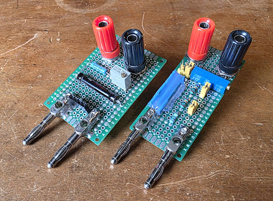
And of course, now I have two 1000:1 voltage dividers. The v1 I leave set to my old Siemens meter, and the v2 I have calibrated to me new meter. I shouldn't struggle measuring high(ish) voltages in the future! 😊
Add Comment
This policy contains information about your privacy. By posting, you are declaring that you understand this policy:
- Your name, rating, website address, town, country, state and comment will be publicly displayed if entered.
- Aside from the data entered into these form fields, other stored data about your comment will include:
- Your IP address (not displayed)
- The time/date of your submission (displayed)
- Your email address will not be shared. It is collected for only two reasons:
- Administrative purposes, should a need to contact you arise.
- To inform you of new comments, should you subscribe to receive notifications.
- A cookie may be set on your computer. This is used to remember your inputs. It will expire by itself.
This policy is subject to change at any time and without notice.
These terms and conditions contain rules about posting comments. By submitting a comment, you agree with these rules:
- Although the administrator will attempt to moderate comments, not all comments can be moderated at all times.
- You acknowledge that all comments express the opinions of the original author and not those of the administrator.
- You will not post material which is knowingly false, obscene, hateful, threatening, harassing or invasive of privacy.
- The administrator has the right to edit, move or remove any comment for any reason and without notice.
Failure to comply with these rules may result in being banned from submitting further comments.
These terms and conditions are subject to change at any time and without notice.
Comments